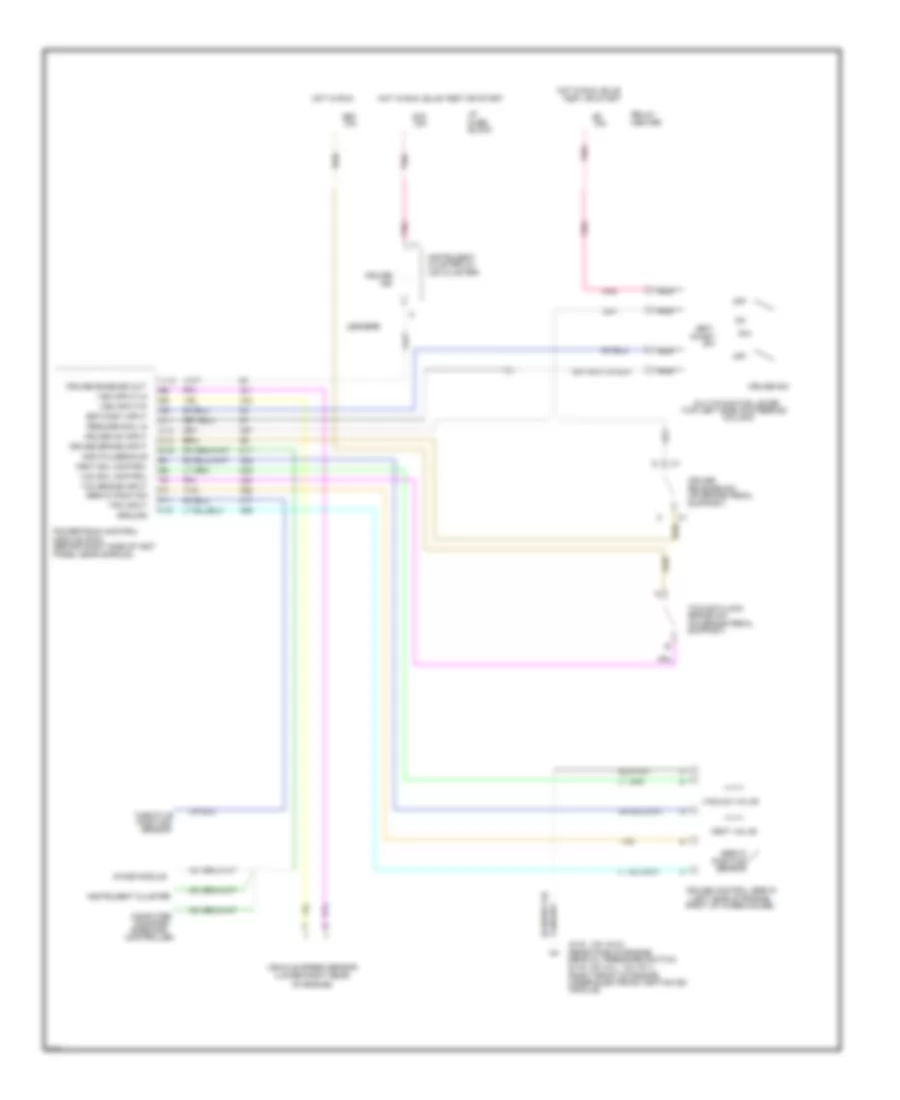
CRUISE CONTROL
Cruise Control Wiring Diagram for Pontiac Bonneville SE 1995
List of elements for Cruise Control Wiring Diagram for Pontiac Bonneville SE 1995:
- #1d
- #5c
- (behind right side of inst
- (left side of engine,
- (lower right rear
- (on brake pedal
- (rear face of engine,
- (right front of engine,
- (top left side of steering
- (v6 vin k)
- (v6 vin l, v6 vin 1)
- 10a
- 15a
- 4000 pulses/mile
- A12
- Block
- Brake sw
- C11
- C12
- C14
- Center
- Chime module
- Cluster (w/
- Coast
- Column)
- Command
- Computer
- Controller
- Cruise
- Cruise
- Cruise brake input
- Cruise control servo
- Cruise enabled out
- Cruise on input
- Cruise sw
- D15
- F11
- F16
- Fuse
- G115
- G119
- Ground
- Hot in run
- Hot in run, bulb
- Hot in run, bulb test or start
- I/p
- Ind
- Instrument
- Instrument cluster
- Lesabre
- Module (pcm)
- Module)
- Multi/function lever
- Nca
- Near oil pressure switch)
- Of engine)
- Off
- Panel near shroud)
- Pnk
- Position
- Powertrain control
- R/a
- Relay
- Release sw
- Resume/accl in
- Ride(ccr)
- Right of wheelhouse)
- Sensor
- Servo
- Servo position
- Set/
- Set/cost input
- Support)
- Tan
- Tcc brake input
- Tcc/anti/lock
- Test or start
- Throttle
- Tps input
- U23 cluster)
- Under electronic ignition (ei)
- Vac sol control
- Vacuum valve
- Vehicle speed sensor
- Vent sol control
- Vent valve
- Vss input/hi
- Vss input/lo
 Čeština
 Dansk
Dansk Deutsch
 Ελληνικά
 English
 English
 Español
 Suomi
Suomi Français
 Français
 עברית
עברית Hrvatski
 Magyar
 Italiano
 日本語
日本語 한국어
한국어 Nederlands
 Português
 Português
 Română
 Русский
 Slovenčina
 Slovenščina
 Svenska
 Türkçe
 中文 (中国)
 Polski