БЛОК ПРЕДОХРАНИТЕЛЕЙ И РЕЛЕ
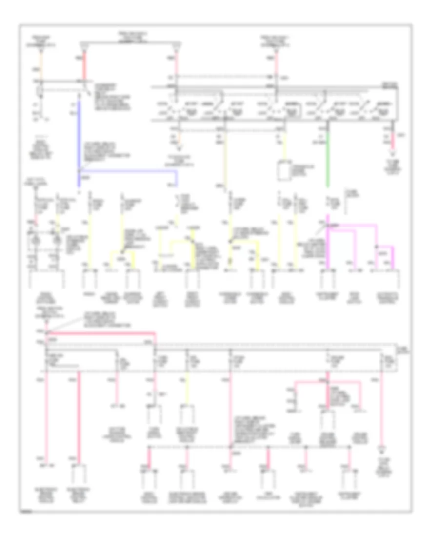
Электросхема блока предохранителей и реле (1 из 4) для Pontiac Grand Prix GTP 1997
 https://portal-diagnostov.com/license.html
Automotive Electricians Portal FZCO
Automotive Electricians Portal FZCO
https://portal-diagnostov.com/license.html
https://portal-diagnostov.com/license.html
Automotive Electricians Portal FZCO
Automotive Electricians Portal FZCO
Электросхема блока предохранителей и реле (1 из 4) для Pontiac Grand Prix GTP 1997 - Список элементов:
- (c60)
- (cj2)
- (i/p harness, behind center of i/p, 17 cm from data link connector breakout)
- (i/p harness, below center of i/p, 27 cm from 10-pin clear connector)
- (right side of i/p cross beam, behind fuse block)
- A12
- Accessory time delay relay (diagram 2 of 4)
- Alt sense fuse 10a
- Aux/ cnsl fuse 15a
- B/u lamp fuse 10a
- B12
- Base
- Batt main 1 maxi fuse 60a
- Batt main 2 maxi fuse 60a
- Battery
- Blower motor control module
- Blower motor resistor
- Body control module
- C60
- Cd chg fuse 10a
- Cig ltr fuse 15a
- Cigar lighter
- Cj2
- Cool fan 1 maxi fuse 30a
- Cool fan 1 relay
- Cool fan 2 maxi fuse 30a
- Cool fan 2 relay
- Cool fan relay
- Data link connector
- E c12
- E12
- Ecm sense fuse 10a
- Electronic brake control module
- Electronic brake control relay
- Floor console accessory power receptacle
- Fog lamp relay
- Fog lp fuse 10a
- Fuel pump fuse 15a
- Fuel pump relay
- Fuse block
- Fusible link (10 ga-rust)
- G201
- Generator
- Hazard fuse 15a
- Headlamp circuit breaker 20a
- Headlamp switch
- Headlamps maxi fuse 60a
- Heater- a/c control
- Horn fuse 15a
- Horn relay
- Hvac hi fuse 30a
- Ign main 1 maxi fuse 40a
- Ign main 2 maxi fuse 60a
- Int lamp fuse 10a
- Low frequency audio amplifier
- Multi disc cd player
- Outside remote control rear view mirror switch
- Park lp fuse 20a
- Powertrain control module
- Pwr mir fuse 10a
- Radio
- Radio fuse 10a
- Rap fuse 10a
- Red
- Remote battery stud
- Remote control door lock receiver
- Roof console accessory power receptacle
- S202
- S238
- S331
- Starter
- Stop lamp fuse 15a
- Stop lamp switch
- Theft deterrent indicator lamp
- Theft deterrent relay
- Theft deterrent shock sensor
- To accessory time delay relay (diagram 2 of 4)
- To fuse block (diagram 4 of 4)
- To ignition switch (diagram 2 of 4)
- To underhood electrical center (diagram 3 of 4)
- Transaxle range switch
- Trip calculator
- Turn signal switch
- Underhood electrical center
- Uplevel (driver seat harness, under right front door sill, 14 cm from 6-pin black connector)
Электросхема блока предохранителей и реле (2 из 4) для Pontiac Grand Prix GTP 1997
Электросхема блока предохранителей и реле (2 из 4) для Pontiac Grand Prix GTP 1997 - Список элементов:
- (2 door) c1
- (4 door)
- (dome lmp harn, 11 cm from reading lamp breakout)
- (i/p harn, behind right side of instrument cluster, 20 cm from driver information display/ trip calculator breakout)
- (i/p harn, below center of i/p, 34 cm from 10-pin clear conn)
- (i/p harn, below i/p, near steering column)
- (i/p harn, below right side of i/p, 1 cm from 56-pin black/gray connector)
- (i/p harn, below right side of i/p, 8 cm from 56-pin black/gray connector breakout)
- 2 door
- 4 door
- Abs ign fuse 10a
- Accessory time delay relay (behind right side of i/p, mounted to i/p cross beam above fuse block)
- Accy
- Automatic transaxle control
- Body control module
- Body control module (below left side of i/p)
- Btsi fuse 10a
- Bulb test
- C13
- C201
- C205
- Cruise control module
- Cruise control release switch
- Cruise fuse 10a
- Daytime running lamps control module
- Driver information display
- Drl fuse 10a
- Ecm fuse 10a
- Electronic brake control indicator lamp driver module
- Electronic brake control module
- Electronic brake control relay
- From ign main 1 maxi fuse (diagram 1 of 4)
- From ign main 2 maxi fuse (diagram 1 of 4)
- From ignition switch (diagram 2 of 4)
- From rap fuse (diagram 1 of 4)
- Fuse block
- H c
- Hot with park lamps on
- I/p-ign fuse 10a
- Ignition switch
- Inflatable restraint control module
- Inflatable steering wheel module coil
- Inside rear view mirror
- Instrument cluster
- Instrument cluster head-up display dimmer switch
- Left front window switch
- Lock
- Mall fuse 10a
- Mall pgm fuse 10a
- Nca
- Off
- Pnk
- Pwr wdo circuit breaker 30a
- Radio
- Radio control switches
- Radio fuse 10a
- Red
- Right front window switch
- Run
- S209
- S220
- S228
- S249
- S264
- S266 (i/p harn, 21 cm from stop lamp switch)
- S310 (body harn, under right frt door sill, 14 cm from 16-pin white connector)
- S376
- S394
- Sir fuse 15a
- Start
- Stop lamp switch
- Str whl ctrl fuse 2a
- Str whl illum fuse 2a
- Sunroof actuator motor
- Sunroof fuse 20a
- To abs fuse (diagram 2 of 4)
- To dic/hvac fuse (diagram 4 of 4)
- To ign main relay (diagram 3 of 4)
- Transaxle range switch
- Trip calculator
- Turn fuse 10a
- Turn signal lever
- Turn signal switch
- Windshield wiper motor
- Windshield wiper switch
- Wiper fuse 25a
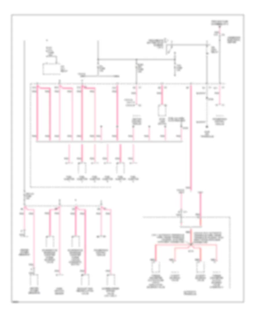
Электросхема блока предохранителей и реле (3 из 4) для Pontiac Grand Prix GTP 1997
Электросхема блока предохранителей и реле (3 из 4) для Pontiac Grand Prix GTP 1997 - Список элементов:
- (fuel inj harn, 44 cm from pcm)
- (vin 1: automatic transaxle harn, inside transaxle housing, 19 cm from 14-pin gray connector)
- (vin k &
- (vin m & vin k: automatic transaxle harn, inside transaxle housing, 19 cm from 7-pin black/clear connector)
- 1-2 shift solenoid valve
- 2-3 shift solenoid valve
- A/c clu fuse 10a
- A/c clu relay
- A12
- Automatic transaxle
- B (vin m)
- B12
- C11
- C12
- D11
- Elek ign fuse 15a
- Evaporative emissions canister purge solenoid valve
- Evaporative emissions canister purge vacuum diagnostic switch
- Exhaust gas recirculation valve
- From ecm fuse (diagram 2 of 4)
- From remote l battery stud (diagram 1 of 4)
- Fuel injector
- G129 (on transaxle)
- Heated oxygen sensor #1
- Heated oxygen sensor #2
- Ign main relay
- Ign1-uh fuse 15a
- Ignition control module
- Inj fuse 10a
- Mass air flow sensor
- Nca
- P vin 1)
- Pnk
- Pnk c10
- Powertrain control module
- Red
- Red a
- S106
- S109
- S115
- Stop lamp switch
- Supercharger bypass valve (vin 1 only)
- Tcc fuse 10a
- Torque converter clutch pulse width modulation solenoid valve
- Torque converter clutch solenoid valve (4t60e-only)
- Underhood electrical center
- Vin 1
- Vin k & vin 1
- Vin k & vin m
- Vin m
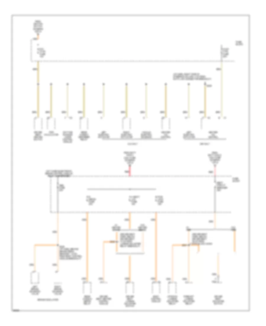
Электросхема блока предохранителей и реле (4 из 4) для Pontiac Grand Prix GTP 1997
Электросхема блока предохранителей и реле (4 из 4) для Pontiac Grand Prix GTP 1997 - Список элементов:
- (driver seat harn, below driver seat, 10 cm from lumbar adjuster relay breakout)
- (driver seat harn, below driver seat, 36 cm from 6-pin black conn)
- (i/p harn, right side of steering column, 4 cm from data link connector breakout)
- Abs fuse 20a
- Body control module
- Brake modulator
- C60 only
- Cj2 only
- Daytime running lamps control module
- Dic/ hvac fuse 10a
- Driver seat adjuster switch
- Driver seat heated switch
- Driver seat heater control module
- Driver seat lumbar adjuster switch
- Fore/aft lumbar adjuster relay
- From batt main 2 maxi fuse (diagram 1 of 4)
- From ignition switch (diagram 2 0f 4)
- Fuse block
- H seat/ lum fuse 15a
- Heater- a/c control
- Hot when electronic brake control module relay is energized
- Hvac ctrl fuse 20a
- Left brake solenoid valve
- Left electric actuator
- Nca
- Pwr lock fuse 15a
- R defog fuse 30a
- Rear window defog relay
- Rear window defogger relay
- Red
- Right brake solenoid valve
- Right electric actuator
- S206
- S235 (i/p harn, behind brake pedal bracket, 15 cm from body control module breakout)
- S331
- S332
- Seat circuit breaker 25a
- Trip calculator
- Up/down lumbar adjuster relay
- Vacuum electric solenoid
- W/ ags
- W/ heated seats
- W/o ags
- W/o heated seats

 Čeština
 Dansk
Dansk Deutsch
 Ελληνικά
 English
 English
 Español
 Suomi
Suomi Français
 Français
 עברית
עברית Hrvatski
 Magyar
 Italiano
 日本語
日本語 한국어
한국어 Nederlands
 Português
 Português
 Română
 Русский
 Slovenčina
 Slovenščina
 Svenska
 Türkçe
 中文 (中国)