СИСТЕМА УСИЛИТЕЛЯ РУЛЯ
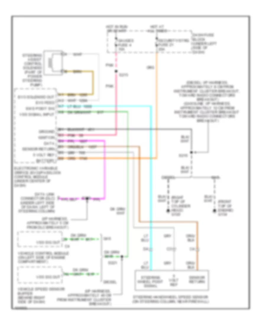
Электросхема усилителя руля для GMC Cab amp; Chassis C2500 1998
Электросхема усилителя руля для GMC Cab amp; Chassis C2500 1998 - Список элементов:
- (diesel: i/p harness, approximately 8 cm from instrument cluster breakout, toward radio connectors breakout) (gasoline: i/p harness, approximately 12 cm from instrument cluster breakout toward radio connectors breakout)
- (front top of engine) g134
- (i/p harness, approximately 40 cm from instrument cluster breakout)
- (i/p harness, approximately 5 cm from dlc breakout)
- (right top of cylinder head) g120
- 5 volt ref
- Battery
- Dash fuse block (under left side of dash)
- Data
- Data link connector (dlc) (under left side of dash, left of steering column)
- Diesel
- Electronic variable orifice (evo)/passlock control module (under center of dash)
- Evo feed
- Evo solenoid out
- Gas
- Gauges fuse 4 10a
- Ground
- Hot at all times
- Hot in run or start
- Ignition
- Pnk
- S213
- S215
- S221
- S280
- Security/strg fuse 21 20a
- Sensor return
- Steering assist control solenoid (part of power steering pump)
- Steering handwheel speed sensor (on steering column, near firewall)
- Steering wheel posit signal
- Sws posit sig
- Vehicle control module (on left side of engine compartment)
- Vehicle speed sensor buffer (behind right side of dash)
- Volt ref
- Vss sig out
- Vss signal input
 Čeština
 Dansk
Dansk Deutsch
 Ελληνικά
 English
 English
 Español
 Suomi
Suomi Français
 Français
 עברית
עברית Hrvatski
 Magyar
 Italiano
 日本語
日本語 한국어
한국어 Nederlands
 Português
 Português
 Română
 Русский
 Slovenčina
 Slovenščina
 Svenska
 Türkçe
 中文 (中国)
 Polski