POWER DISTRIBUTION
Power Distribution Wiring Diagram (1 of 2) for Audi A4 1996

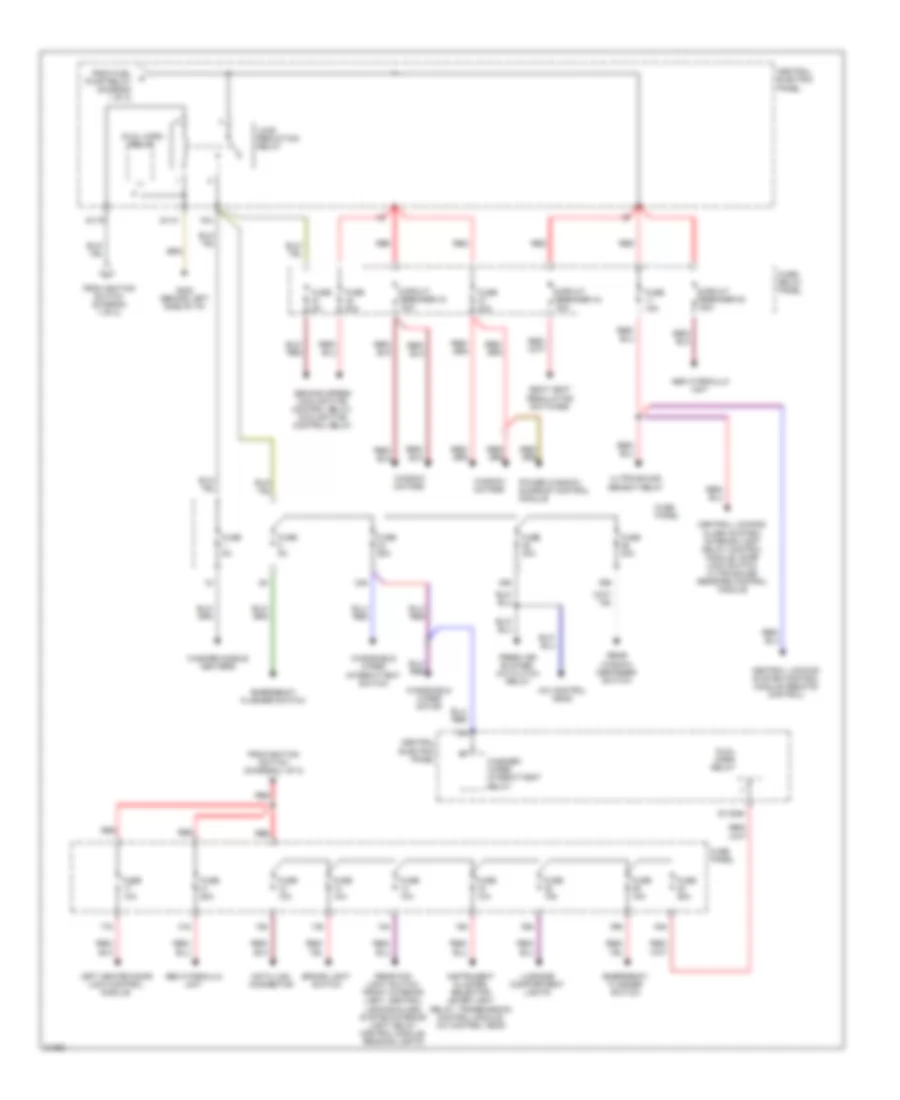
List of elements for Power Distribution Wiring Diagram (1 of 2) for Audi A4 1996:
- (not used)
- 16a
- 28a
- 29a
- 30a
- 31a
- 32a
- 33a
- 34a
- 37a
- 50b
- 86s
- 87f
- Abs control module
- Acc
- Air bag control module, transmission control module, power window/ sunroof control module, window motors
- Anti-slip control switch, traction control indicator light
- Back-up light switch, automatic transmission control light, multi-function transmission range switch
- Battery
- Central electric panel
- Central locking/ alarm system/ interior light delay control module
- Central locking/ alarm system/ interior light delay control module, door lock switch, central locking control module (remote control)
- Cigarette lighter
- Engine control module
- Evap canister purge regulator valve, intake manifold change-over valve, egr vacuum regulator solenoid valve, oxygen sensors
- Fuel injectors
- Fuel pump
- Fuel pump relay
- Fuse 10a
- Fuse 15a
- Fuse 20a
- Fuse 5a
- Fuse panel
- G202 (behind left side of i/p)
- Generator
- Generator, instrument cluster
- Headlight dimmer/ flasher switch
- Headlight washer system relay
- Ignition coils, engine control module, mass air flow sensor
- Ignition switch
- Instrument cluster, radio, central locking/alarm system/interior light delay control module
- Instrument cluster, rear lamp control module, outside air temperature display
- Interior lights system
- Key-in ignition switch
- Light switch
- Malfunction indicator lamp (mil), mirror adjustment switch, seat heat regulating switches
- Off
- Park/ neutral position relay
- Power sunroof control module
- Radio
- Red
- Run
- S1/50z
- S2/87f
- S3/15
- S3/s
- S4/4
- S4/50z
- S4/b
- S6/50a
- Shift lock solenoid, cruise control switch
- Start
- Starter
- To fuse (diagram 2 of 2)
- To load reduction relay (diagram 2 of 2)
Power Distribution Wiring Diagram (2 of 2) for Audi A4 1996
List of elements for Power Distribution Wiring Diagram (2 of 2) for Audi A4 1996:
- 12a
- 13a
- 14a
- 15a
- 17a
- 24a
- 25a
- 26a
- 38a
- 39a
- 40a
- 41a
- 75a
- 75x
- A/c control head
- Abs hydraulic unit
- Brake light switch
- Central electric panel
- Central locking system control module (remote control)
- Central locking/ alarm system/ interior light delay control module, door lock switch, ultra-sound sensors control module
- Circuit breaker 43 30a
- Circuit breaker 44 30a
- Circuit breaker 53 50a
- Data link connector
- Dual horn relay
- Emergency flasher switch
- Fresh air blower, a/c clutch relay
- From fuel pump relay (diagram 1 of 2)
- From ignition switch (diagram 1 of 2)
- Fuse 10a
- Fuse 15a
- Fuse 25a
- Fuse 30a
- Fuse 40a
- Fuse 5a
- Fuse panel
- Fuse/ relay panel
- G202 (behind left side of i/p)
- Instrument cluster, selector lever light relay, transmission control module, a/c control head
- Left heated door lock control module
- Load reduction relay
- Luggage compartment lights
- Power window/ sunroof control module
- Rear fog light switch, front interior light, central locking/alarm system/interior light delay control module, reading lights
- Rear window defogger switch
- Red
- S1/30ah
- S1/31
- S1/75
- Seat heat regulating switches
- Second speed coolant fan control relay, coolant fan control relay
- Ultra-sound sensot relay
- Washer nozzle heaters
- Washer/ wiper intermittent relay
- Window motors
- Windshield wiper intermittent switch
- Windshield wiper motor