POWER DISTRIBUTION
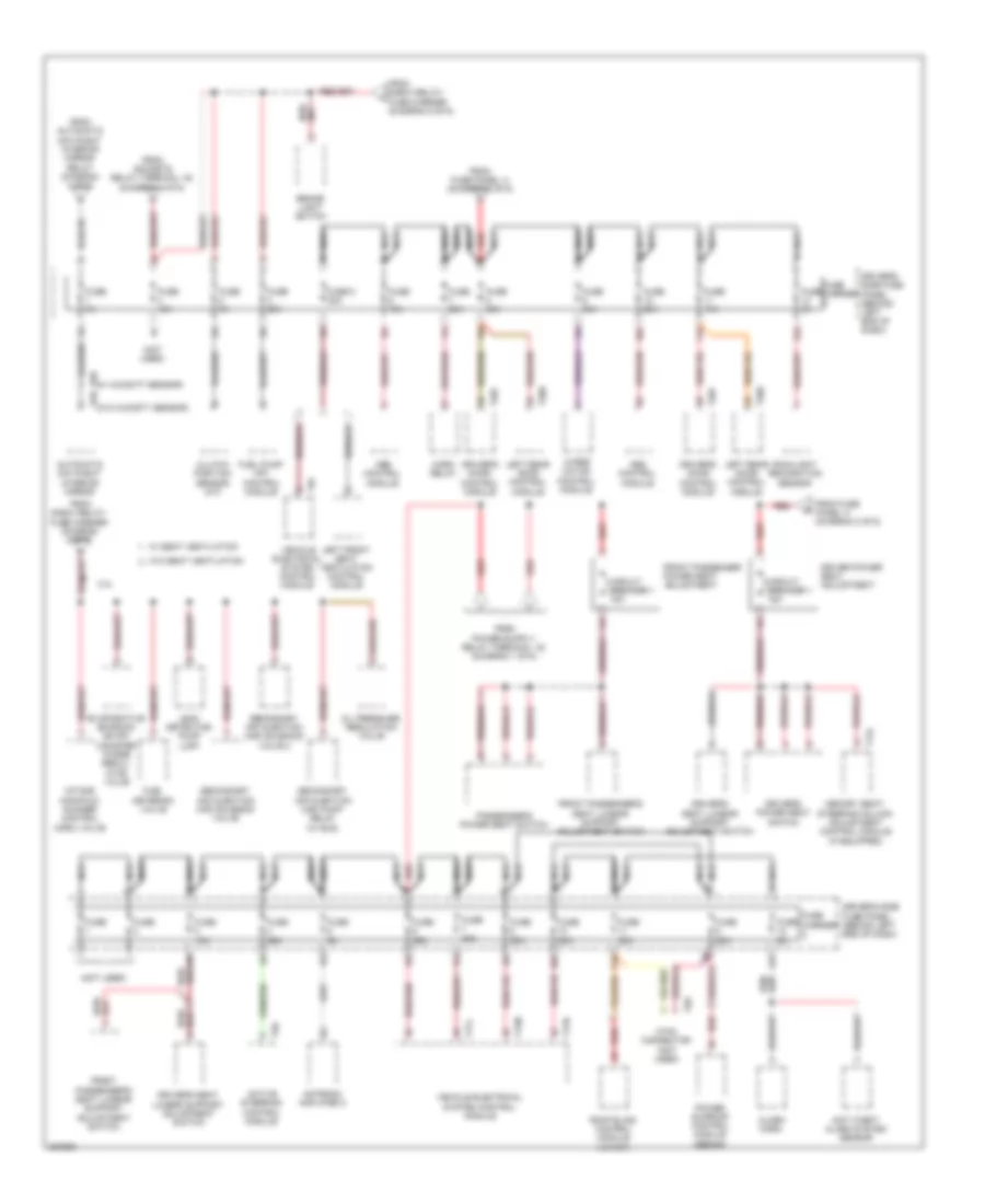
Power Distribution Wiring Diagram (1 of 6) for Audi A4 2.0T Avant Quattro 2010

List of elements for Power Distribution Wiring Diagram (1 of 6) for Audi A4 2.0T Avant Quattro 2010:
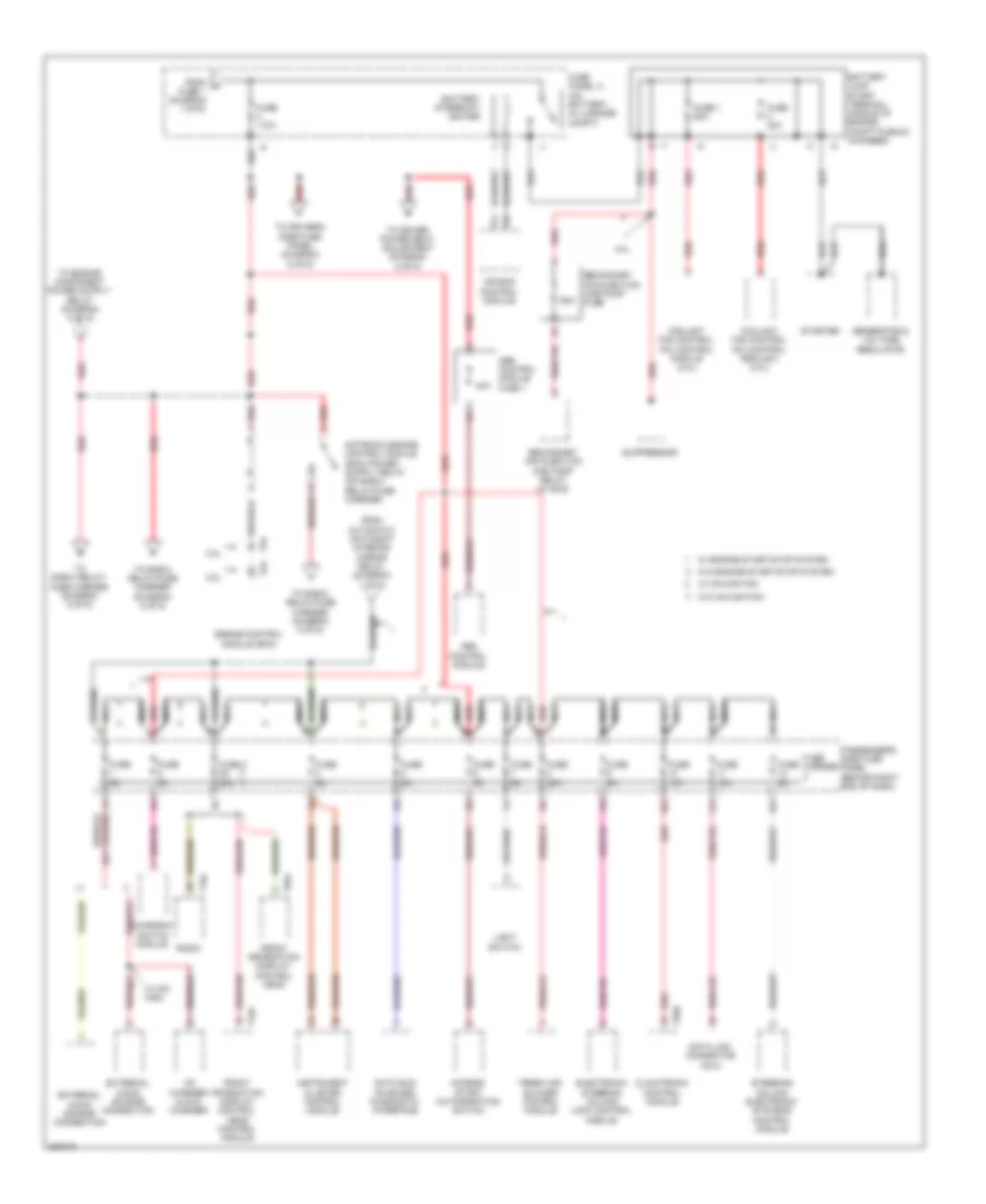
Power Distribution Wiring Diagram (2 of 6) for Audi A4 2.0T Avant Quattro 2010
List of elements for Power Distribution Wiring Diagram (2 of 6) for Audi A4 2.0T Avant Quattro 2010:
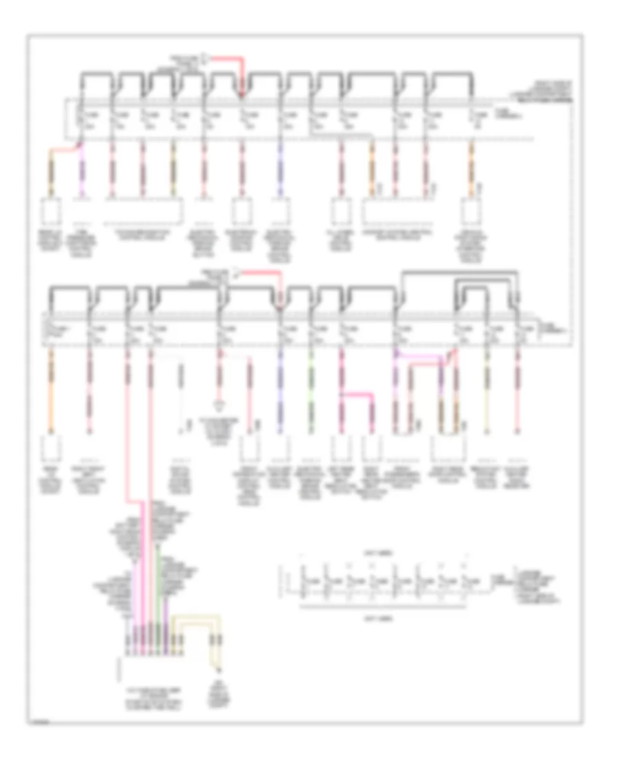
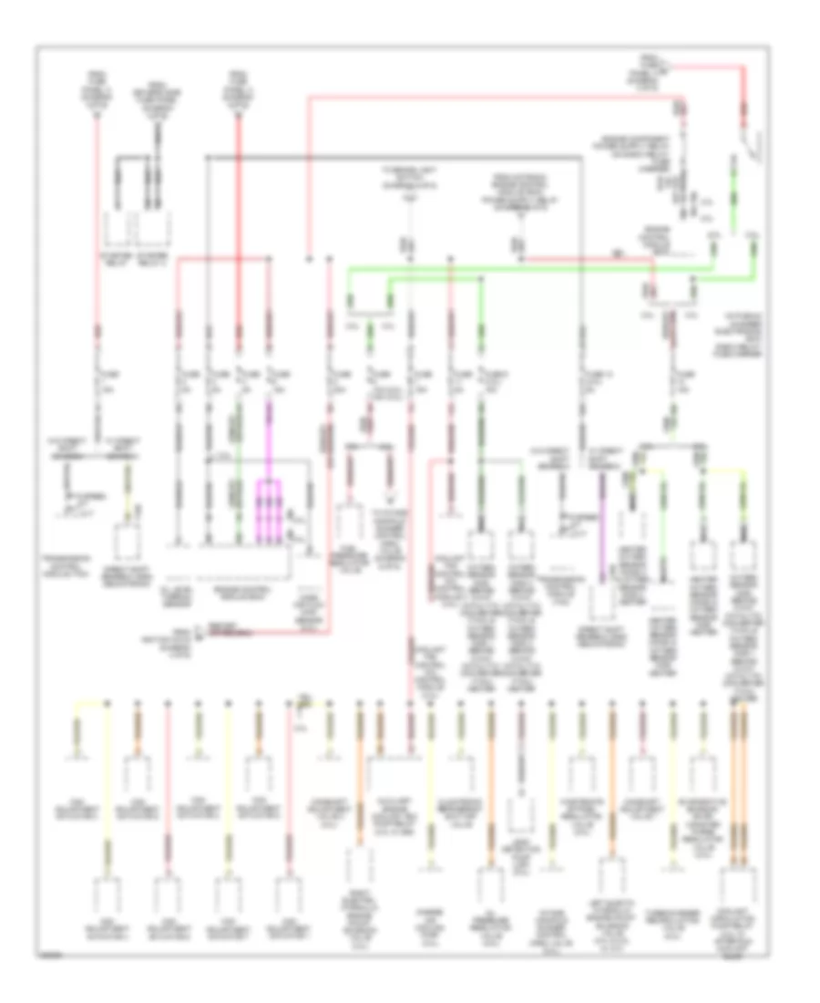
Power Distribution Wiring Diagram (3 of 6) for Audi A4 2.0T Avant Quattro 2010
List of elements for Power Distribution Wiring Diagram (3 of 6) for Audi A4 2.0T Avant Quattro 2010:
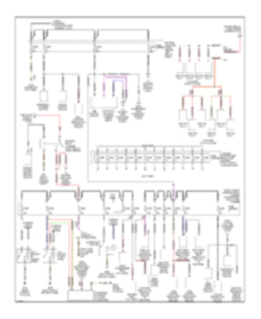
Power Distribution Wiring Diagram (4 of 6) for Audi A4 2.0T Avant Quattro 2010
List of elements for Power Distribution Wiring Diagram (4 of 6) for Audi A4 2.0T Avant Quattro 2010:
Power Distribution Wiring Diagram (5 of 6) for Audi A4 2.0T Avant Quattro 2010
List of elements for Power Distribution Wiring Diagram (5 of 6) for Audi A4 2.0T Avant Quattro 2010:
Power Distribution Wiring Diagram (6 of 6) for Audi A4 2.0T Avant Quattro 2010
List of elements for Power Distribution Wiring Diagram (6 of 6) for Audi A4 2.0T Avant Quattro 2010: