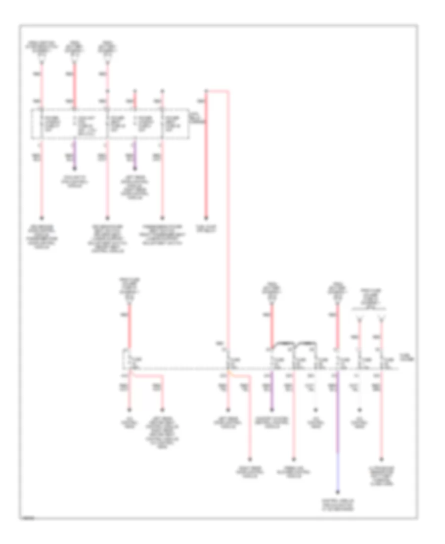
POWER DISTRIBUTION
Power Distribution Wiring Diagram (1 of 2) for Audi A4 Quattro 2002

List of elements for Power Distribution Wiring Diagram (1 of 2) for Audi A4 Quattro 2002:
- (1.8l) (3.0l)
- (lower right "a" pillar)
- (lower right "b" pillar)
- 10a
- 12a
- 14a
- 150a
- 22a
- 243a
- 30a
- 31a
- 33a
- 35a
- 36a
- 37a
- 50a
- 50b
- 86s
- 9-pin relay carrier (in instrument panel)
- A/c control head
- Abs control module (w/edl)
- Abs control module fuse 1
- Air quality sensor, high pressure sensor
- Airbag control module
- Back-up light switch, automatic day/night interior mirror, data link connector (dlc), shift lock solenoid, multi-function transmission range (tr) switch
- Battery
- Brake booster relay
- Brake light switch
- Brake light switch, clutch vacuum vent valve switch, abs control module
- Cigarette lighter
- Control module w/ indicator unit instrument panel insert
- Control module w/ indicator unit instrument panel insert, steering column electronic systems control module
- Data link connector (dlc)
- Driver side door control module
- Fuel pump (fp) relay
- Fuse 10a
- Fuse 15a
- Fuse 20a
- Fuse 30a
- Fuse 50a 40a
- Fuse 5a
- Fuse holder
- Fuse strip (main fuse)
- Generator
- Headlight range control module
- Ignition/starter switch
- Light switch
- Load reduction relay
- Motronic engine control module (ecm)
- Nca
- Oil level thermal sensor, telephone/telematic control module, board computer function selector switch ii, tiptronic switch, transmission control module, multi-function transmission range (tr) switch, rear window shade switch, telephone control module for operating electronics, control module for navigation w/ cd-mechanism, left rear heated seat control module, right rear heated seat control module
- Park/neutral position (pnp) relay
- Passenger side door control module
- Rear shade circuit breaker 10a
- Rear window shade control module
- Rear windshield wiper motor
- Red
- Red b
- Red c
- Red d
- Relay carrier e-box
- Secondary air injection (air) pump relay
- Servotronic control module
- Socket
- Starter
- Starter, locking relay for starter (clutch pedal switch), starter interlock alarm system relay
- Steering column electronic systems control module
- Sunroof motor
- T10b
- T32b
- Telephone amplifier
- Telephone/ telematic control module, telephone control module for operating electronics
- To 4-pin relay carrier (diagram 2 of 2)
- To fuse (diagram 2 of 2)
- To fuse holder (diagram 2 of 2)
- Transmission control module (tcm)
- Vehicle electrical system control module
- Washer nozzle heater (left/right)
Power Distribution Wiring Diagram (2 of 2) for Audi A4 Quattro 2002
List of elements for Power Distribution Wiring Diagram (2 of 2) for Audi A4 Quattro 2002:
- (1.8l)
- 23a
- 24a
- 25a
- 26a
- 38a
- 4-pin relay carrier
- 44a
- A/c control head
- Comfort system central control module
- Control module for navigation w/ cd mechanism
- Coolant fan fuse 42 40a 60a (3.0l)
- Coolant fc (fan control) module
- Driver side door control module, passenger side door control module
- Driver's power seat switch, driver's seat lumbar support adjustment switch, memory seat control module
- Fresh air blower control module
- From battery (diagram 1 of 2)
- From fuse holder fuse 30 (diagram 1 of 2)
- From fuse holder fuse 33 (diagram 1 of 2)
- From ignition/ starter switch (diagram 1 of 2)
- Fuel pump (fp) relay
- Fuse 10a
- Fuse 15a
- Fuse 20a
- Fuse 30a
- Fuse holder
- Left rear door control module
- Left rear door control module, right rear door control module
- Left rear heated seat control module, right rear heated seat control module, a/c control head
- Nca
- Passenger's power seat switch, front passenger seat lumbar support adjustment switch
- Power seat fuse 45 30a
- Power seat fuse 46 30a
- Power window fuse 2 30a
- Power window fuse 37 30a
- Red
- Right rear door control module
- Ultra-sound sensor for anti-theft warning, alarm horn