POWER DISTRIBUTION
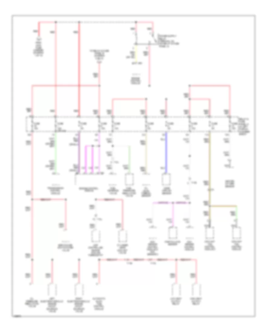
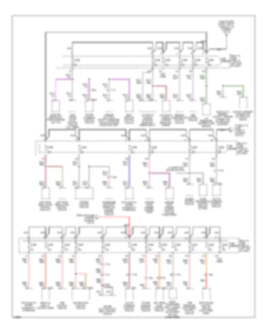
Power Distribution Wiring Diagram (1 of 10) for Audi A6 Premium Plus 2014

List of elements for Power Distribution Wiring Diagram (1 of 10) for Audi A6 Premium Plus 2014:
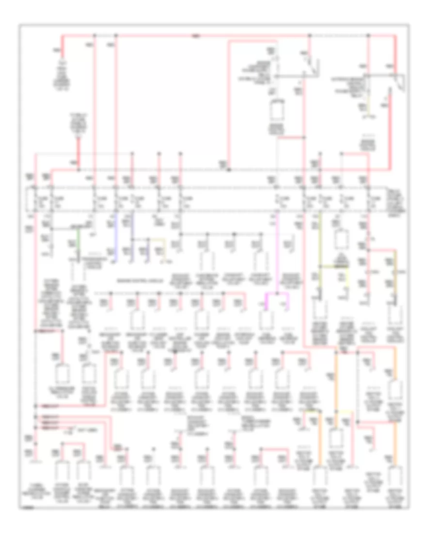
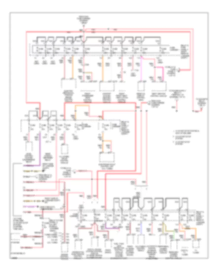
Power Distribution Wiring Diagram (2 of 10) for Audi A6 Premium Plus 2014
List of elements for Power Distribution Wiring Diagram (2 of 10) for Audi A6 Premium Plus 2014:
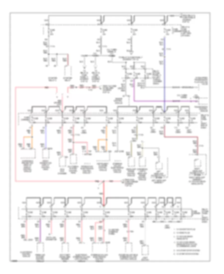
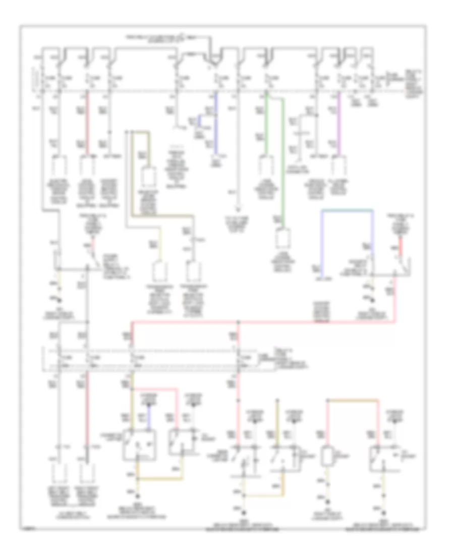
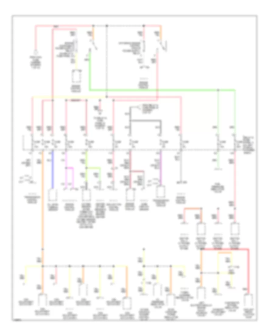
Power Distribution Wiring Diagram (3 of 10) for Audi A6 Premium Plus 2014
List of elements for Power Distribution Wiring Diagram (3 of 10) for Audi A6 Premium Plus 2014:
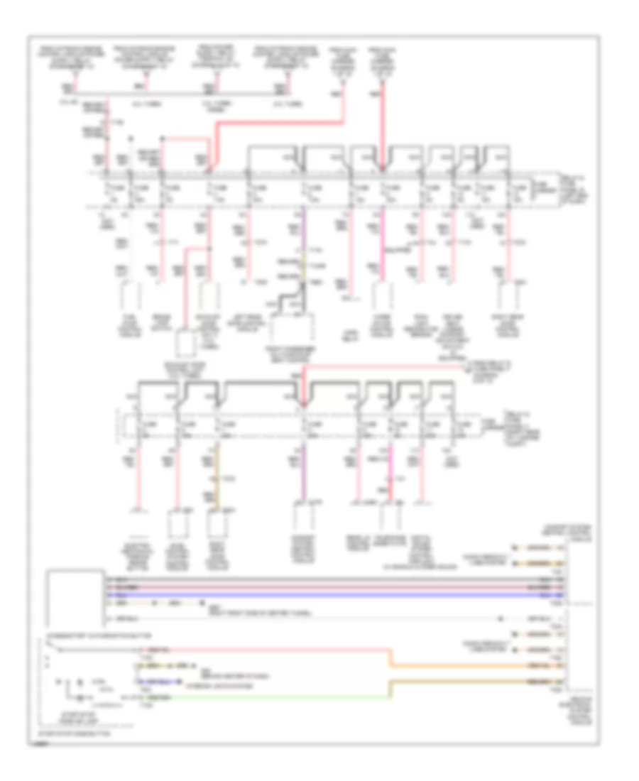
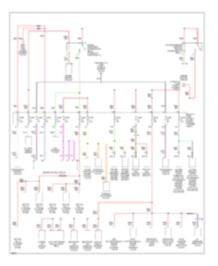
Power Distribution Wiring Diagram (4 of 10) for Audi A6 Premium Plus 2014
List of elements for Power Distribution Wiring Diagram (4 of 10) for Audi A6 Premium Plus 2014:
Power Distribution Wiring Diagram (5 of 10) for Audi A6 Premium Plus 2014
List of elements for Power Distribution Wiring Diagram (5 of 10) for Audi A6 Premium Plus 2014:
Power Distribution Wiring Diagram (6 of 10) for Audi A6 Premium Plus 2014
List of elements for Power Distribution Wiring Diagram (6 of 10) for Audi A6 Premium Plus 2014:
Power Distribution Wiring Diagram (7 of 10) for Audi A6 Premium Plus 2014
List of elements for Power Distribution Wiring Diagram (7 of 10) for Audi A6 Premium Plus 2014:
Power Distribution Wiring Diagram (8 of 10) for Audi A6 Premium Plus 2014
List of elements for Power Distribution Wiring Diagram (8 of 10) for Audi A6 Premium Plus 2014:
Power Distribution Wiring Diagram (9 of 10) for Audi A6 Premium Plus 2014
List of elements for Power Distribution Wiring Diagram (9 of 10) for Audi A6 Premium Plus 2014:
Power Distribution Wiring Diagram (10 of 10) for Audi A6 Premium Plus 2014
List of elements for Power Distribution Wiring Diagram (10 of 10) for Audi A6 Premium Plus 2014: