POWER DISTRIBUTION
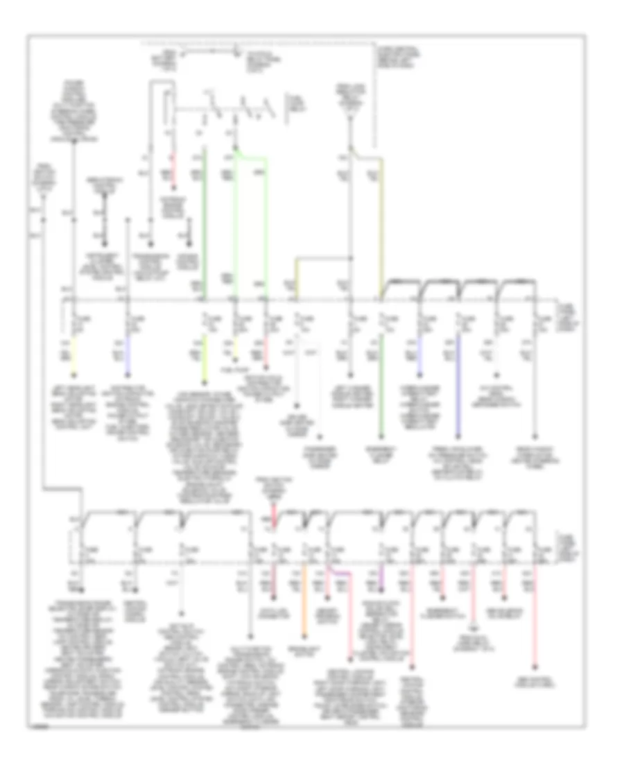
Power Distribution Wiring Diagram (1 of 3) for Audi A6 Quattro 2001

List of elements for Power Distribution Wiring Diagram (1 of 3) for Audi A6 Quattro 2001:
- (not used)
- 33a
- 50b
- 86s
- Battery
- Central locking control module, clutch pedal position switch, multi function transmission range switch, 4-low range control module (allroad)
- Cigarette lighter
- Dual horn relay
- Foglight switch
- Fuse 15a
- Fuse 200a
- Fuse panel (left side of dash)
- G900 (lower left "a" pillar)
- Headlight adjustment control module
- Headlight dimmer/ flasher switch
- High beam headlights, high beam indicator, foglights
- Horn button
- Ignition switch
- Instrument cluster, central locking control module, steering column/ belt height adjustment control module
- Instrument cluster, generator
- Instrument cluster, glove compartment light, a/c control head license plate lamps (w/o drl)
- Interior lights system
- Key-in ignition switch
- Left parking light, left taillight, instrument cluster, lamp control module, license plate lamps (w/ drl)
- Light light switch switch
- Load reduction relay
- Low & high tone horn
- Micro central electric panel (behind left side of dash)
- Off
- Rear cigarette lighter
- Red
- Right low beam headlight, left low beam headlight, lamp control module
- Right parking light, right taillight, instrument cluster, lamp control module
- Run
- S1/
- S1/ 30ah
- S2/ 87h
- Start
- Starter
- Starter, level control module
- Starting interlock relay (13-fold relay panel)
- To fuel pump relay (diagram 2 of 3)
- To fuse 12 (diagram 2 of 3)
- To fuse 142 (diagram 3 of 3)
- To fuse 40 (diagram 2 of 3)
- To fuse 5 (diagram 2 of 3)
- To fuse panel (diagram 2 of 3)
- Voltage regulator/ generator (4.2l only)
- Voltage regulator/ generator (except 4.2l)
- Wiper/washer intermittent relay
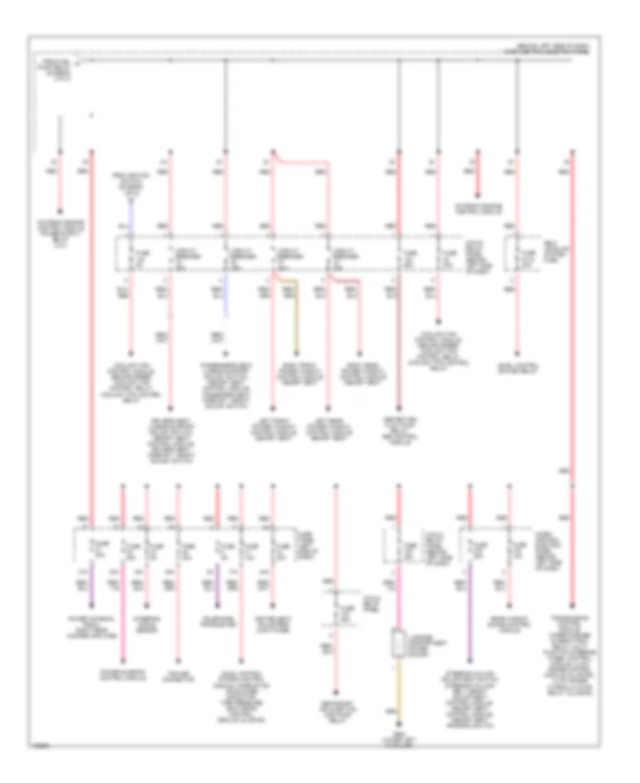
Power Distribution Wiring Diagram (2 of 3) for Audi A6 Quattro 2001
List of elements for Power Distribution Wiring Diagram (2 of 3) for Audi A6 Quattro 2001:
- 10a
- 12a
- 13a
- 14a
- 15a
- 24a
- 25a
- 26a
- 27a
- 28a
- 29a
- 31a
- 32a
- 34a
- 38a
- 39a
- 40a
- 41a
- 42a
- 75x
- 87a
- 87f
- A/c control head, rear window defogger switch
- Abs control module (w/edl)
- Abs solenoid valve relay
- Air bag control module
- Analog clock, solar cell separation relay, memory mirror control module, selector level light relay, instrument cluster, navigation control module
- Anti-slip control switch, abs control module, brake light switch, clutch vacuum vent valve switch (m/t), motronic engine control module, air quality sensor, level control system control head, level control system control module, asr/esp button
- Brakelight switch
- Central locking conrol module
- Central locking control module, interior monitoring sensors control module
- Central locking control module, right door warning light, left door warning light, passenger compartment monitoring switch, trunk lid release switch, driver & passenger seat memory control head
- Data link connector
- Distributor ignition capacitor, motronic engine control module, power output stage, fuel injectors, cruise control switch
- Driver side heated outside mirror
- Emergency flasher relay
- Emergency flasher switch
- Fresh air blower, a/c pressure switch, a/c control head, solar cell separation relay, a/c clutch relay
- From dual horn relay (diagram 1 of 2)
- From e battery (diagram 1 of 3)
- From ignition switch (diagram 1 of 3)
- From load reduction relay (diagram 1 of 3)
- Fuel pump
- Fuel pump relay
- Fuse 10a
- Fuse 15a
- Fuse 20a
- Fuse 25a
- Fuse 30a
- Fuse 5a
- Fuse panel (left side of dash)
- Ignition coils, distributor ignition capacitor, power output stage
- Instrument cluster, level control system control module
- Left headlight beam adjusting motor, right headlight beam adjusting motor, beam adjusting control unit
- Left washer nozzle heater, right washer nozzle heater
- Maf sensor, intake manifold change-over valve, leak detection pump, camshaft adjust valve 1, camshaft adjust valve 2, evap emission canister purge regulator valve, oxygen sensor heaters, secondary air injection solenoid valve, secondary air injection pump relay, intake manifold tuning valve, idle air control valve, exhaust temperature sensors, electro hydraulic engine mount solenoid valve, wastegate bypass regulator valve
- Memory program switch
- Micro central electric panel (behind left side of dash)
- Motronic engine control module
- Multi function transmission range switch, a/c control head, motronic engine control module, shift lock solenoid, tiptronic switch, day/night interior mirror, back-up light switch, data link connector, garage door opener control module, emergency flasher switch
- Nca
- Passenger side heated outside mirror
- Power window control modules, multi function steering wheel control module, tire pressure monitoring control module (allroad)
- Rear window wiper motor, heated steering wheel
- Red
- Servotronic control module
- To 8-fold relay panel (diagram 3 of 3)
- Transmission control module, vacuum pump relay (a/t)
- Transmission range selector lever display, outside air temperature display, outside air temperature sensor a/c control head, lamp control module, heated driver's seat adjuster, heated passenger's seat adjuster, mirror fold-away function control module, radio, mirror adjustment switch, rear window shade switch, telephone transceiver, radio, oil level thermal sensor, lamp control module, parking aid control module, navigation control module
- Wiper/washer intermittent relay, wiper/washer switch, wiper/washer intermittent regulator
Power Distribution Wiring Diagram (3 of 3) for Audi A6 Quattro 2001
List of elements for Power Distribution Wiring Diagram (3 of 3) for Audi A6 Quattro 2001:
- (behind left side of dash) micro central electric panel
- 16a
- 17a
- 3-fold relay panel
- 30a
- 35a
- 37a
- 44a
- 8-fold relay panel (behind left side of dash)
- Abs return flow pump relay, abs control module
- Circuit breaker 30a
- Coolant fan control module, second speed coolant fan control relay, coolant fan control relay
- Driver's seat lumbar support adjust switch, memory seat control module, driver's seat fore/aft height adjust switch
- From fuel g pump relay (diagram 2 of 3)
- From ignition switch (diagram 1 of 3)
- Fuse 10a
- Fuse 20a
- Fuse 30a
- Fuse 40a
- Fuse 50a
- Fuse 5a
- Fuse panel (left side of dash)
- Fuse s110 40a
- G900 (lower left "a" pillar)
- Heated seat adjusters & switches
- Left front power window control module memory seat
- Left rear power window control module memory seat
- Level control system control module, combustion air blower capacitor, tire pressure monitoring control module (allroad)
- Level control system relay
- Luggage compartment power socket
- Micro- central electric panel (behind left side of dash)
- Motronic engine control module
- Passenger's seat lumbar support adjust switch, memory seat control module, passenger seat fore/aft height adjust switch
- Power antenna, radio, right rear woofer amplifier
- Power sunroof control module
- Rear window shade control module
- Red
- Right front power window control module memory seat
- Right rear power window control module memory seat
- Secondary air injection (air) pump relay
- Self leveling system fuse
- Steering angle sensor
- Steering column adjustment switch, steering column/ belt height adjustment control module, memory seat control module, memory seat program switch
- Telephone transceiver
- Trailer connector
- Transmission control module, wiper/washer intermittent relay, multi function steering wheel control module, 4-low range control module (allroad), 4-low range hydraulic pump relay (allroad)