POWER DISTRIBUTION
Power Distribution Wiring Diagram (1 of 2) for Audi RS 4 2007

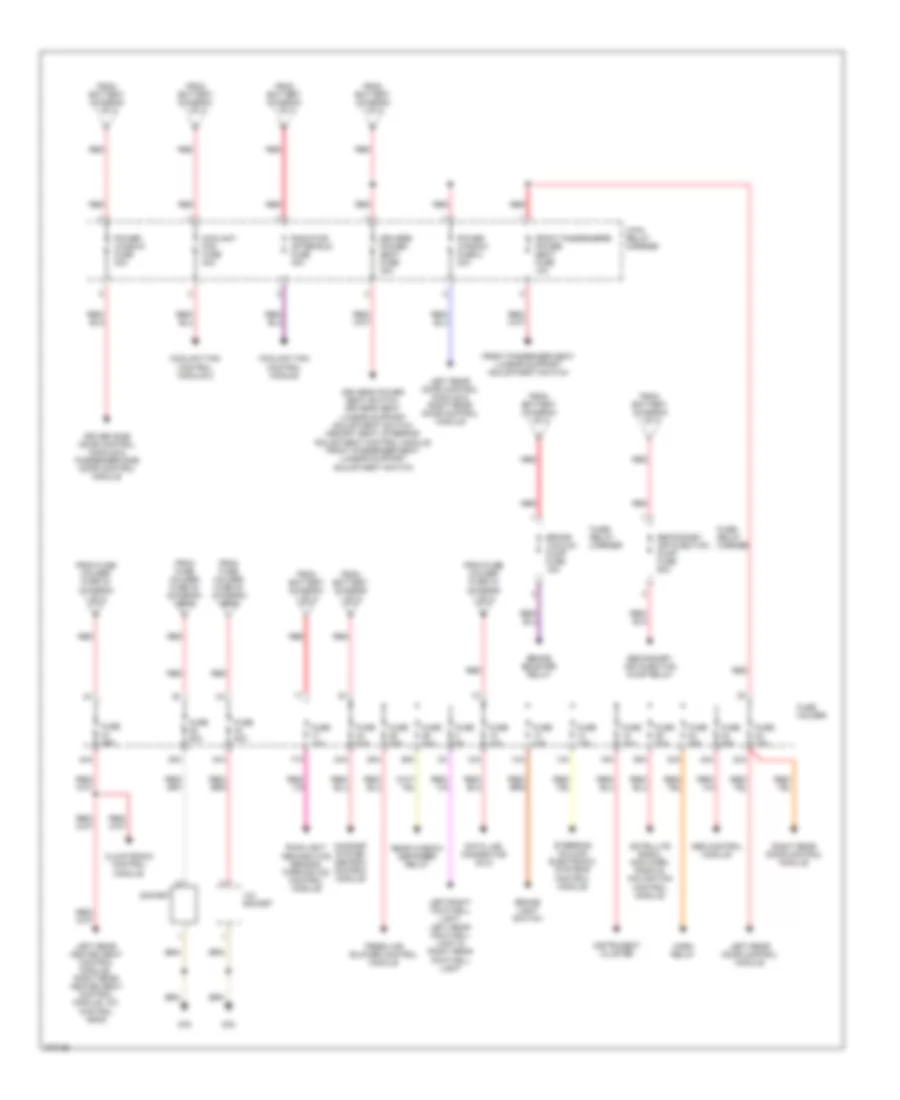
List of elements for Power Distribution Wiring Diagram (1 of 2) for Audi RS 4 2007:
- (w/ heated front window) windshield heating voltage converter
- 10a
- 11a
- 16a
- 18a
- 22a
- 243a
- 30a
- 31a
- 33a
- 36a
- 37a
- 38a
- 50b
- 86s
- 9-pin relay carrier
- Abs control module
- Abs control module fuse 1
- Acc
- Air quality sensor & high pressure sensor
- Alarm horn & comfort system central control module
- Back-up light switch, data link connector (dlc), automatic day/
- Battery
- Cigarette lighter
- Climatronic control module
- Driver side door control module
- Engine control module (ecm)
- Engine control module (ecm) i & ii
- Engine control module (ecm) i & start system button
- Esp sensor unit abs control module, anti-slip control switch
- Front passenger side door control module
- Fuse 10a
- Fuse 150a
- Fuse 15a
- Fuse 20a
- Fuse 30a
- Fuse 40a
- Fuse 5a
- Fuse holder
- Fuse strip (main fuse)
- G33
- G49
- G701
- Garage door opener control head & garage door opener control module
- Generator
- Headlight range control module, headlight adjuster, left headlight beam adjusting motor, right headlight beam adjusting motor, right headlight power output stage
- Ignition/starter switch
- Instrument cluster
- Instrument cluster & steering column electronic systems control module
- Left headlamp assembly
- Light switch
- Load reduction relay
- Lock
- Nca
- Night interior mirror,
- Off
- Oil level thermal sensor, rear window
- On off
- Power sunroof control module
- Rear shade circuit breaker 10a
- Rear window shade control module
- Red
- Red b
- Seat control module, right rear heated seat control module
- Seat occupied recognition pressure sensor & front passenger's airbag disabled indicator lamp air bag control module
- Servotronic control module
- Shade switch, left rear heated
- Sport program button
- Start
- Start system button
- Starter
- Starter relay & starter relay 2
- Steering column electronic systems control module
- T10b
- T32b
- Telephone amplifier
- Telephone transceiver
- To 4-pin relay carrier (diagram 2 of 2)
- To brake vacuum pump fuse (diagram 2 of 2)
- To fuse holder (diagram 2 of 2)
- To secondary air injection pump fuse (diagram 2 of 2)
- Vehicle electrical system control module
- Washer nozzle heater (left/right)
Power Distribution Wiring Diagram (2 of 2) for Audi RS 4 2007
List of elements for Power Distribution Wiring Diagram (2 of 2) for Audi RS 4 2007:
- 12a
- 12v socket
- 13a
- 14a
- 15a
- 17a
- 23a
- 24a
- 25a
- 26a
- 34a
- 35a
- 39a
- 4-pin relay carrier
- 40a
- 42a
- 44a
- Abs control module
- Brake booster relay
- Brake light switch
- Brake vacuum pump fuse 15a
- Climatronic control module
- Comfort system central control module
- Coolant fan control module
- Coolant fan control module 2
- Coolant fan fuse 40a
- Data link connector (dlc)
- Driver side door control module & passenger side door control module
- Driver's power seat fuse 30a
- Driver's power seat switch, driver's seat lumbar support adjustment switch, memory seat/ steering adjustment control module, front passenger seat lumbar support adjustment switch
- Fresh air blower control module
- From battery (diagram 1 of 2)
- From fuse holder fuse 30 (diagram 1 of 2)
- From fuse holder fuse 33 (diagram 1 of 2)
- Front passenger seat lumbar support adjustment switch
- Front passenger's power seat fuse 10a
- Fuse 10a
- Fuse 15a
- Fuse 20a
- Fuse 25a
- Fuse 30a
- Fuse 35a
- Fuse 5a
- Fuse holder
- Fuse/ relay carrier
- G33
- G78
- Horn relay
- Instrument cluster
- Left rear door control module
- Left rear door control module & right rear door control module
- Left rear heated seat control module, right rear heated seat control module, a/c control head
- Left/right footwell light, left rear footwell light & right rear footwell light
- Power window fuse 2 30a
- Power window fuse 30a
- Radiator after-run fuse 40a
- Rain/light recognition sensor, parking aid control module
- Rear window defogger relay
- Red
- Right rear door control module
- Satellite radio, amplifier, radio & navigation control module
- Secondary air injection pump fuse 50a
- Secondary air injection pump relay
- Socket
- Steering column electronic systems control module