AUTOMOTIVE ELECTRICIANS PORTAL

POWER DISTRIBUTION – BMW 750i 2012 – SYSTEM WIRING DIAGRAMS

POWER DISTRIBUTION

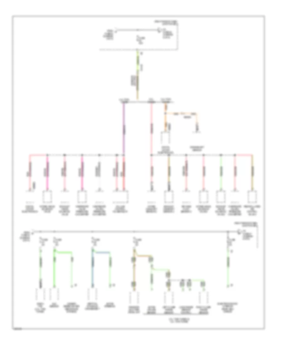
Power Distribution Wiring Diagram (1 of 8) for BMW 750i 2012

Power Distribution Wiring Diagram (1 of 8) for BMW 750i 2012Download PDF file

List of elements for Power Distribution Wiring Diagram (1 of 8) for BMW 750i 2012:

  • (right rear of luggage compt) rear distribution box
  • 11b
  • 12b
  • 15b
  • 1b jump start terminal point
  • 25b
  • 3.0l twin turbo
  • 4.4l twin
  • Alternator
  • Battery
  • Bi-stable relay
  • Boot lid lift
  • Central gateway module
  • Compressor relay
  • Computer data lines system
  • Diagnosis socket
  • Dme main relay
  • Driver electronic outer door handle module
  • Dynamic stability control (dsc)
  • Electric fan cut-out relay
  • Electronics junction box
  • Evolution electronic contact free tailgate opening
  • Except 3.0l twin turbo
  • Except 4.4l twin
  • Except hybrid
  • Footwell module
  • From fuse box (diagram 1 of 8)
  • From terminal 15n f
  • From terminal 30b e
  • Fuse 100a
  • Fuse 10a
  • Fuse 150a
  • Fuse 20a
  • Fuse 250a
  • Fuse 30a
  • Fuse 40a
  • Fuse 5a
  • Fuse 60a
  • Fuse box (center of luggage compt)
  • Fuse holder (right front of engine compt)
  • Fuse n/a
  • Ignition & fuel injection relay
  • Ignition & fuel injection load shedding relay
  • Intelligent battery sensor (under center of luggage compt)
  • Junction box (right side of dash)
  • Left headlight
  • Left rear electric auxiliary heater
  • Natural vaccum leak detection (early production)
  • Natural vaccum leak detection (late production)
  • Nca
  • Parking brake control module
  • Passenger electronic outer door handle module
  • Power distribution
  • Rear axle king pin inclination control
  • Rear compartment fan motor output stage
  • Rear driver's side outer door handle electronic module
  • Rear passenger's side outer door handle electronic module
  • Red
  • Red/
  • Relay (diagram 7 of 8)
  • Relay (diagram 8 of 8)
  • Right headlight
  • Safety battery terminal generator
  • Secondary air pump relay (6.0l turbo)
  • Siren w/ tilt alarm sensor
  • Starter
  • To fuse (diagram 7 of 8)
  • To fuse 14 (diagram 2 of 8)
  • To fuse 4 (diagram 2 of 8)
  • To rear distribution box (diagram 1 of 8)
  • Top hifi amplifier
  • Trailer module
  • Transfer box (except hybrid 4.4l twin turbo)
  • Transfer terminal point
  • Turbo
  • Valvetronic relay
  • X10272
  • X13 3b
  • X168 1b
  • X19 1b
  • X28 1b
  • X5 1b
  • X8 1b
  • X9 1b
  • Z10 8b (right rear of luggage compt)

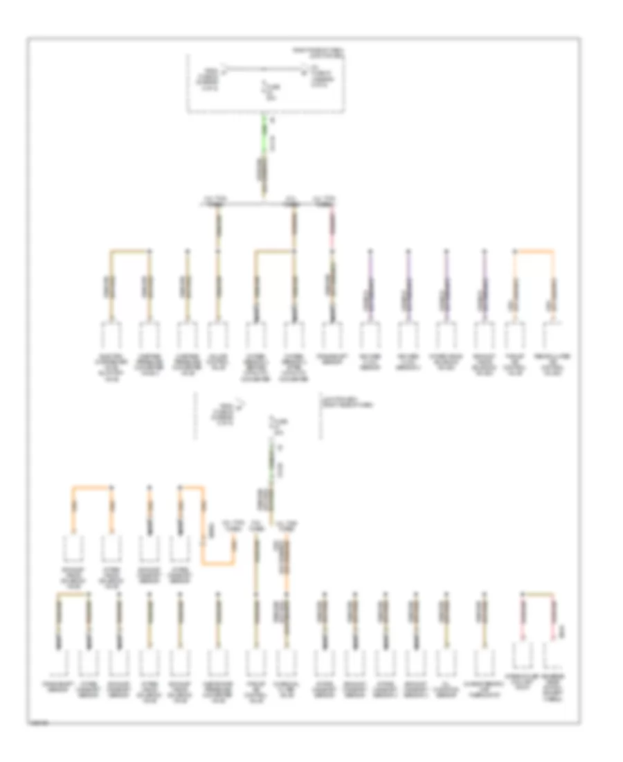
Power Distribution Wiring Diagram (2 of 8) for BMW 750i 2012

List of elements for Power Distribution Wiring Diagram (2 of 8) for BMW 750i 2012:

  • (right side of dash) junction box
  • 10b
  • 12b
  • 13b
  • 6.0l
  • Active steering
  • Basic variant roof functions module
  • Blower output stage
  • Car access system
  • Combox
  • Computer data lines system
  • Controller
  • Coolant pump intercooler (4.4l twin turbo except hybrid)
  • Driver assistance systems control panel
  • Dvd changer
  • Dynamic stability control (dsc)
  • Electric fan cut out relay (except hybrid)
  • Electronics junction box
  • Footwell module
  • From b bi-stable relay (diagram 1 of 8)
  • From c fuse 1 (diagram 1 of 8)
  • From g fuse 71 (diagram 2 of 8)
  • From terminal 15n relay (diagram 3 of 8)
  • Fuel filter heating (except hybrid)
  • Fuse 10a
  • Fuse 15a
  • Fuse 20a
  • Fuse 30a
  • Fuse 40a
  • Fuse 50a
  • Fuse 5a
  • Fuse 60a
  • Fuse 7.5a
  • Glove compartment light
  • Head-up display
  • Heating/air conditioning system
  • High variant roof functions module
  • Instrument cluster control
  • Inter cooler coolant pump (except 3.0l)
  • Light switch unit
  • N2 1b
  • Nca
  • Noise suppressor filter
  • Parking brake button
  • Red
  • Steering column switch cluster
  • Telematic communication box
  • Telematic control unit
  • Telematics
  • Terminal 30b relay
  • To fuse (diagram 2 of 8)
  • To fuse 66 (diagram 3 of 8)
  • To terminal 15n relay (diagram 3 of 8)
  • Trailer module
  • Turbo
  • Unit
  • Vertical dynamics management
  • Video switch (if equipped)
  • W/ basic variant roof functions module
  • W/ high variant roof functions module
  • W/ telematic communication box
  • Washer pump relay
  • X13 1b
  • X60562
  • Z10 6b (right kick panel)

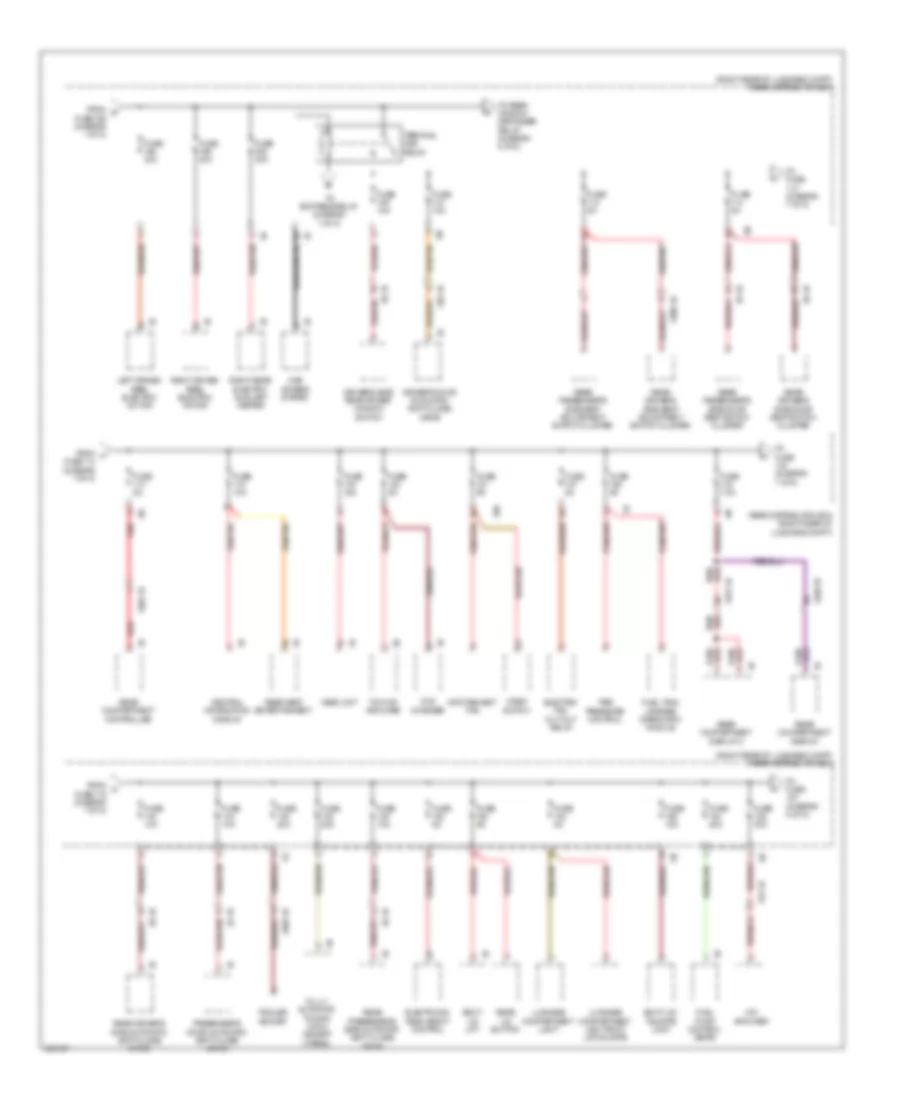
Power Distribution Wiring Diagram (3 of 8) for BMW 750i 2012

List of elements for Power Distribution Wiring Diagram (3 of 8) for BMW 750i 2012:

  • (right kick panel) z10 6b
  • (right side of dash) junction box
  • 10b
  • 12 v connection
  • 3.0l twin turbo
  • 3.0l twin turbo & except hybrid 4.4l twin turbo
  • 6.0l & hybrid 4.4l twin turbo
  • Basic variant roof functions module
  • Car access system
  • Driver's door seat switch cluster (w/ memory)
  • Driver's door switch block
  • Driver's seat module
  • Driver's side seat adjustment switch cluster (w/ multi- function seat)
  • Electronic transmission control
  • Electronics junction box
  • Except hybrid
  • From k fuse 28 (diagram 2 of 8)
  • From l fuse 54 (diagram 3 of 8)
  • From washer h pump relay (diagram 2 of 8)
  • Front cigarette lighter 12 v connection
  • Fuse 10a
  • Fuse 15a
  • Fuse 20a
  • Fuse 30a
  • Fuse 5a
  • Fuse 7.5a
  • Gear selector switch
  • High variant roof function module (if equipped)
  • High variant roof functions module
  • Horn relay
  • Hybrid
  • Instrument cluster control unit
  • Integrated chassis management
  • Interior lights system
  • Junction box (right side of dash)
  • Left headlight
  • Left rear vanity mirror light
  • Nca
  • Passenger's door seat switch cluster
  • Passenger's seat module
  • Passenger's side seat adjustment switch cluster
  • Rear cigarette lighter 12 v connection
  • Red
  • Right exterior mirror
  • Right rear vanity mirror light
  • Steering column switch cluster
  • Terminal 15n relay
  • To fuse 21 (diagram 4 of 8)
  • To fuse 35 (diagram 4 of 8)
  • To horn relay (diagram 3 of 8)
  • To terminal 30b relay (diagram 2 of 8)
  • W/ basic variant roof functions module
  • W/ high variant roof functions module
  • Wiper module
  • X12 1b
  • X13 3b
  • X14 1b
  • X28 1b
  • X5 1b
  • Z10 6b (right kick panel)

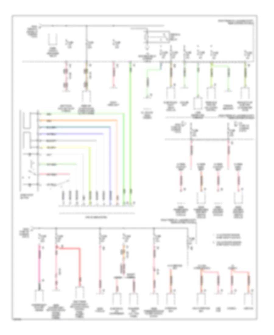
Power Distribution Wiring Diagram (4 of 8) for BMW 750i 2012

List of elements for Power Distribution Wiring Diagram (4 of 8) for BMW 750i 2012:

  • (4.4l twin turbo) (6.0l turbo)
  • (right side of dash) junction box
  • 10b
  • 3.0l twin turbo
  • 4.4l twin turbo
  • 6.0l turbo
  • Air mass flow sensor
  • Characteristic map thermo start
  • Characteristic map thermostat
  • Digital motor electronics
  • Digital motor electronics 2
  • Eject box
  • Engine beather heater 1
  • Except 6.0l turbo
  • Extendible dash board speaker
  • From m fuse 67 (diagram 3 of 8)
  • From n fuse 24 (diagram 3 of 8)
  • Fuse 10a 15a
  • Fuse 20a
  • Fuse 30a
  • Fuse 5a
  • Intercooler coolant pump
  • Junction box (right side of dash)
  • Left driven reel electric motor
  • Nca
  • Oil condition sensor
  • Oxygen sensor 2 after catalytic converter
  • Oxygen sensor 2 before catalytic converter
  • Oxygen sensor after catalytic converter
  • Oxygen sensor before catalytic converter
  • Rear compartment automatic climate control
  • Rear driver's side seat heating switch
  • Rear eject box
  • Rear eject box 2
  • Rear passenger's side seat heating switch
  • Red
  • Right driven reel electric motor
  • Secondary air pump relay
  • Starter/ alternator electronics (hybrid)
  • Tank vent valve
  • To fuse 22 (diagram 5 of 8)
  • Volume control valves relay
  • W/ rear compartment automatic climate control
  • W/ rear keypad handset
  • W/o rear compartment automatic climate control
  • X13 1b
  • X13 2b
  • X167 1b
  • X20003
  • X5030
  • X60002
  • X60563
  • X60564
  • X6342

Power Distribution Wiring Diagram (5 of 8) for BMW 750i 2012

List of elements for Power Distribution Wiring Diagram (5 of 8) for BMW 750i 2012:

  • (right side of dash) junction box
  • 3.0l twin turbo
  • 3.0l twin turbo & 4.4l twin turbo
  • 4.4l twin turbo
  • 6.0l turbo
  • Active cruise sensor
  • Active steering
  • Air mass flow sensor 2
  • Auc sensor
  • Camera based driver assistance systems
  • Crankshaft sensor
  • Digital motor electronics
  • E-box fan (3.0l twin turbo)
  • Electrochromic interior rear view mirror
  • Exhaust camshaft sensor 2
  • Exhaust vanos solenoid valve
  • Exhaust vanos solenoid valve 2
  • From o fuse 20 (diagram 4 of 8)
  • From q fuse 42 (diagram 6 of 8)
  • Fuse 30a
  • Fuse 5a
  • Intake camshaft sensor 2
  • Intake vanos solenoid valve
  • Intake vanos solenoid valve 2
  • Left close range sensor
  • Long range sensor control
  • Nca
  • Radiator shutter drive unit
  • Recirculated air control valve 2
  • Right close range sensor
  • To fuse 42 (diagram 6 of 8)
  • To fuse 47 (diagram 6 of 8)
  • Vertical dynamics management
  • Volume control valves relay
  • Wastegate valve 2 pressure converter
  • Wastegate valve pressure converter
  • X13 1b
  • X60002
  • X60564

Power Distribution Wiring Diagram (6 of 8) for BMW 750i 2012

List of elements for Power Distribution Wiring Diagram (6 of 8) for BMW 750i 2012:

  • (right side of dash) junction box
  • 3.0l twin turbo
  • 4.4l twin turbo
  • 6.0l turbo
  • Air mass flow sensor
  • Air mass flow sensor 2
  • Characteristic map thermostat
  • Charcoal filter valve
  • Crankshaft sensor
  • Electric changeover valve, blow-off valve
  • Exhaust camshaft sensor
  • Exhaust camshaft sensor 2
  • Exhaust vanos solenoid valve
  • Exhaust vanos solenoid valve 2
  • From p fuse 22 (diagram 5 of 8)
  • From r fuse 48 (diagram 5 of 8)
  • Fuse 20a
  • Fuse 30a
  • Intake camshaft sensor
  • Intake camshaft sensor 2
  • Intake vanos solenoid valve
  • Intake vanos solenoid valve 2
  • Intercooler coolant pump
  • Junction box (right side of dash)
  • Nca
  • Oil condition sensor
  • Oxygen sensor 2 after catalytic converter
  • Oxygen sensor 2 before catalytic converter
  • Recirculated air control valve 2
  • Reverse gear switch (except hybrid)
  • Thrust air control valve
  • To fuse 43 (diagram 5 of 8)
  • Valume control valve
  • Wastage pressure converter valve
  • Wastage pressure converter valve 2
  • Waste gate pressure converter valve
  • X13 1b
  • X13 2b
  • X60584
  • X8616

Power Distribution Wiring Diagram (7 of 8) for BMW 750i 2012

List of elements for Power Distribution Wiring Diagram (7 of 8) for BMW 750i 2012:

  • (right rear of luggage compt) rear distribution box
  • 10b
  • Boot lid lift
  • Boot lid/ tailgate lock
  • Car access system
  • Central information display
  • Driver's door automatic soft close drive
  • Driver's side rear power window switch
  • Dvd changer
  • Electric fan cut-out relay
  • Electronic ride height control
  • From d fuse 195 (diagram 1 of 8)
  • From t fuse 114 (diagram 7 of 8)
  • From u fuse 116 (diagram 7 of 8)
  • Fuel pump control (ekps)
  • Fuel tank leakage diagnostic module
  • Fully automatic towing hitch (except hybrid)
  • Fuse 10a
  • Fuse 15a
  • Fuse 20a
  • Fuse 30a
  • Fuse 5a
  • Fuse 7.5a
  • Head unit
  • Hifi amplifier
  • Infotainment fan
  • Left driven reel electric motor
  • Luggage compartment light
  • Luggage compartment light boot lid/tailgate
  • Passenger's door automatic soft close drive
  • Rear compartment controller
  • Rear compartment display
  • Rear compartment display 2
  • Rear distribution box (right rear of luggage compt)
  • Rear driver's side automatic soft close drive
  • Rear driver's side door seat switch cluster
  • Rear driver's side seat adjustment switch cluster
  • Rear lid button
  • Rear passenger's side automatic soft close drive
  • Rear passenger's side door seat switch cluster
  • Rear passenger's side seat adjustment switch cluster
  • Rear seat entertainment
  • Red
  • Right driven reel electric motor
  • Right rear electric auxiliary heater
  • Terminal 30b relay
  • Tire pressure control
  • To bi-stable relay (diagram 1 of 8)
  • To fuse (diagram 7 of 8)
  • To fuse (diagram 8 of 8)
  • To rear window defogger relay (diagram 8 of 8)
  • Top hifi amplifier
  • Trailer socket
  • Video switch
  • X19 1b
  • X200 1b
  • X230 1b
  • X231 1b
  • X268 1b
  • X28 1b
  • X5 1b
  • X8 1b
  • X9 1b

Power Distribution Wiring Diagram (8 of 8) for BMW 750i 2012

List of elements for Power Distribution Wiring Diagram (8 of 8) for BMW 750i 2012:

  • (right rear of luggage compt) rear distribution box
  • 10b
  • 11b
  • Additional coolant pump (hybrid)
  • All round vision camera
  • Car access system
  • Combox
  • Cooler box
  • Electrical a/c compressor
  • Electronic night vision module
  • Except hybrid
  • Exhaust flap electric changeover valve
  • From s terminal 30b relay (diagram 7 of 8)
  • From v fuse 185 (diagram 7 of 8)
  • From w fuse 188 (diagram 8 of 8)
  • Fuse 10a
  • Fuse 15a
  • Fuse 20a
  • Fuse 30a
  • Fuse 5a
  • High interface box
  • Hybrid
  • Independent auxiliary heater
  • Interface box
  • Lane departure warning
  • Nca
  • Parking assistant
  • Rear air- conditioning system power output stage
  • Rear axle king pin inclination control
  • Rear compartment air conditioning system (except hybrid)
  • Rear driver's side seat heating module
  • Rear driver's side seat module
  • Rear passenger's side power window switch
  • Rear passenger's side seat heating module
  • Rear passenger's side seat module
  • Rear window defogger relay
  • Red
  • Right headlight
  • Right rear compartment air conditioning control panel (except hybrid)
  • Start-stop button
  • Terminal 15n relay
  • To bi-stable relay (diagram 1 of 8)
  • To fuse 142 (diagram 8 of 8)
  • Transfer box (4.4l twin turbo)
  • Usb hub
  • Video module
  • W/ automatic engine start-stop function
  • W/ combox
  • W/ high interface box
  • W/ interface box
  • W/ rear basic seat
  • W/ rear comfort seat
  • W/o automatic engine start-stop function
  • X13 2b
  • X13 3b
  • X25 1b
  • X9 1b