POWER DISTRIBUTION
3.8L VIN 2
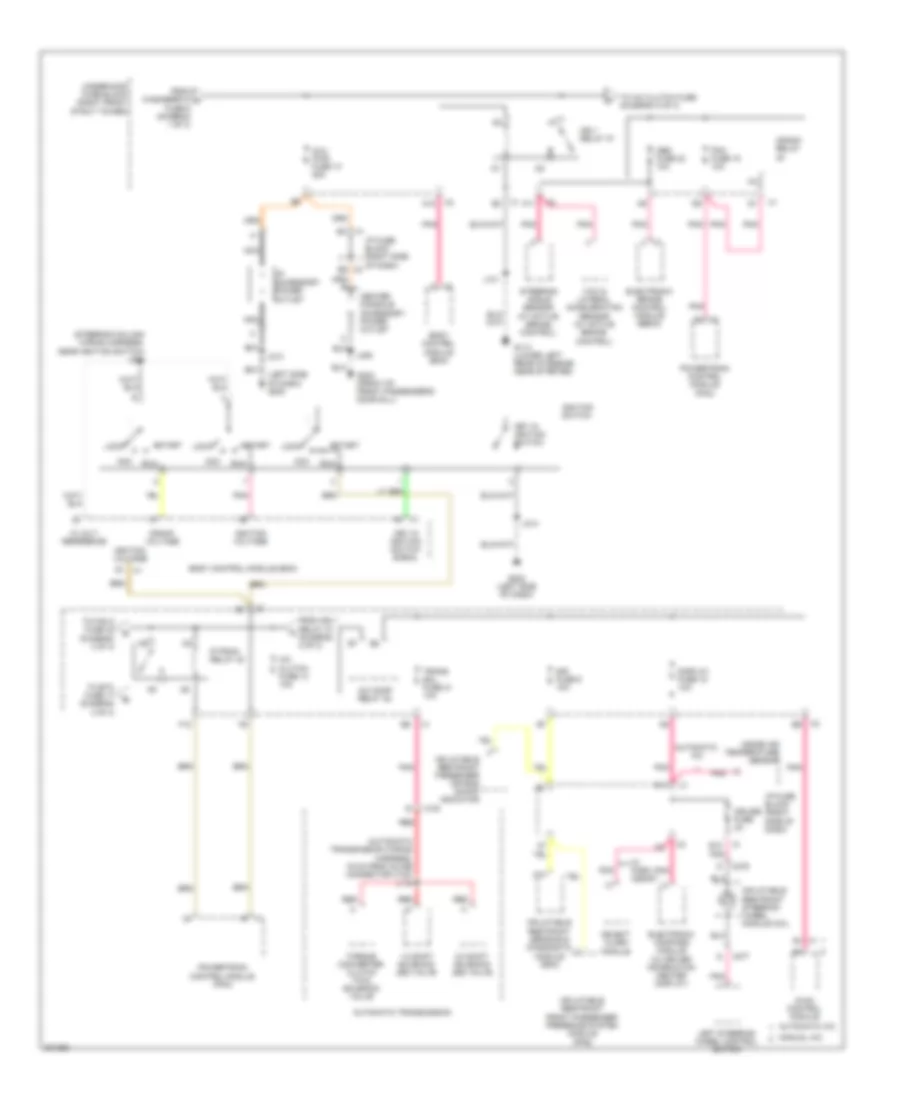
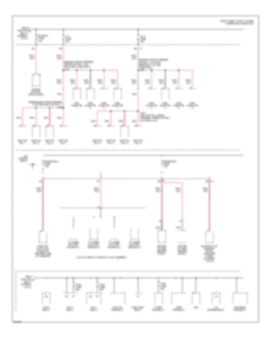
3.8L VIN 2, Power Distribution Wiring Diagram (1 of 3) for Buick Allure CXL 2009

List of elements for 3.8L VIN 2, Power Distribution Wiring Diagram (1 of 3) for Buick Allure CXL 2009:
- (approximately 5 cm from breakout to g302)
- (driver seat wiring harness,
- (right front strut tower) underhood fuse block
- (sunroof wiring harness, 7.5 cm from sunroof motor)
- 4.5 cm from breakout to seat lumbar switch) j331
- A1 x1
- Abs mtr fuse 31 40a
- Abs sol fuse 19 25a
- Air pump fuse 25 50a
- Audio amplifier (w/ 9 speaker system)
- Automatic a/c
- B10
- Batt main 1 fuse 26 40a
- Batt main 2 fuse 27 50a
- Batt main 3 fuse 28 40a
- Batt main 4 fuse 30 30a
- Battery
- Blower motor control module
- Body control module (bcm)
- C10
- Chmsl/ bkup fuse 15a
- Clstr fuse 10a
- Cnstr fuse 10a
- D10
- Data link connector (dlc)
- Digital radio receiver
- Dr/lck trunk fuse 15a
- Driver heated seat relay (if equipped)
- Driver seat adjuster switch
- Driver seat lumbar switch
- Driver window switch
- E x2
- E12
- Electronic brake control module (ebcm) (w/ abs)
- Evaporative emission (evap) canister vent solenoid valve
- F10
- Generator
- Hazrd fuse 20a
- Htd/ seat fuse 20a
- Hvac control module
- Hvac fuse 10a
- I/p fuse block (right side of dash)
- Inflatable restraint passenger presence system (pps) module
- Inside rearview mirror
- Instrument panel cluster (ipc)
- Int/ illum fuse 10a
- J395
- Manual a/c
- Nca
- Onstar/ aldl fuse 10a
- Outside rear- view mirror switch
- Park switch (floor console front compartment)
- Passenger heated seat relay (if equipped)
- Passenger seat adjuster switch (if equipped)
- Passenger window switch
- Pcm/ etc fuse 16 15a
- Power lumbar control seat
- Powertrain control module (pcm)
- Prk/ lamp relay
- Prk/ switch fuse 5a
- Prk/lamp fuse 10a
- Pwr/ mir fuse 10a
- Pwr/ seat circuit breaker 25a
- Pwr/wndw circuit breaker 25a
- R/ defog relay
- Radio
- Rap relay
- Rdo/ amp fuse 25a
- Red
- Remote control door lock receiver (rcdlr)
- Rfa/ mod fuse 10a
- S/roof fuse 20a
- Secondary air injection (air) pump relay (w/ california pzev emission system)
- Starter
- Sunroof motor
- To tcm fuse 8 (diagram 2 of 3)
- Vehicle communication interface module (vcim) (w/ onstar)
- W/ digital audio system
- W/ driver
- W/ sunroof
- W/o digital audio system
- W/o driver
- W/o sunroof
- Washer/ rvc fuse 6 15a
- X1 d12
- X2 f9
- X4 c2
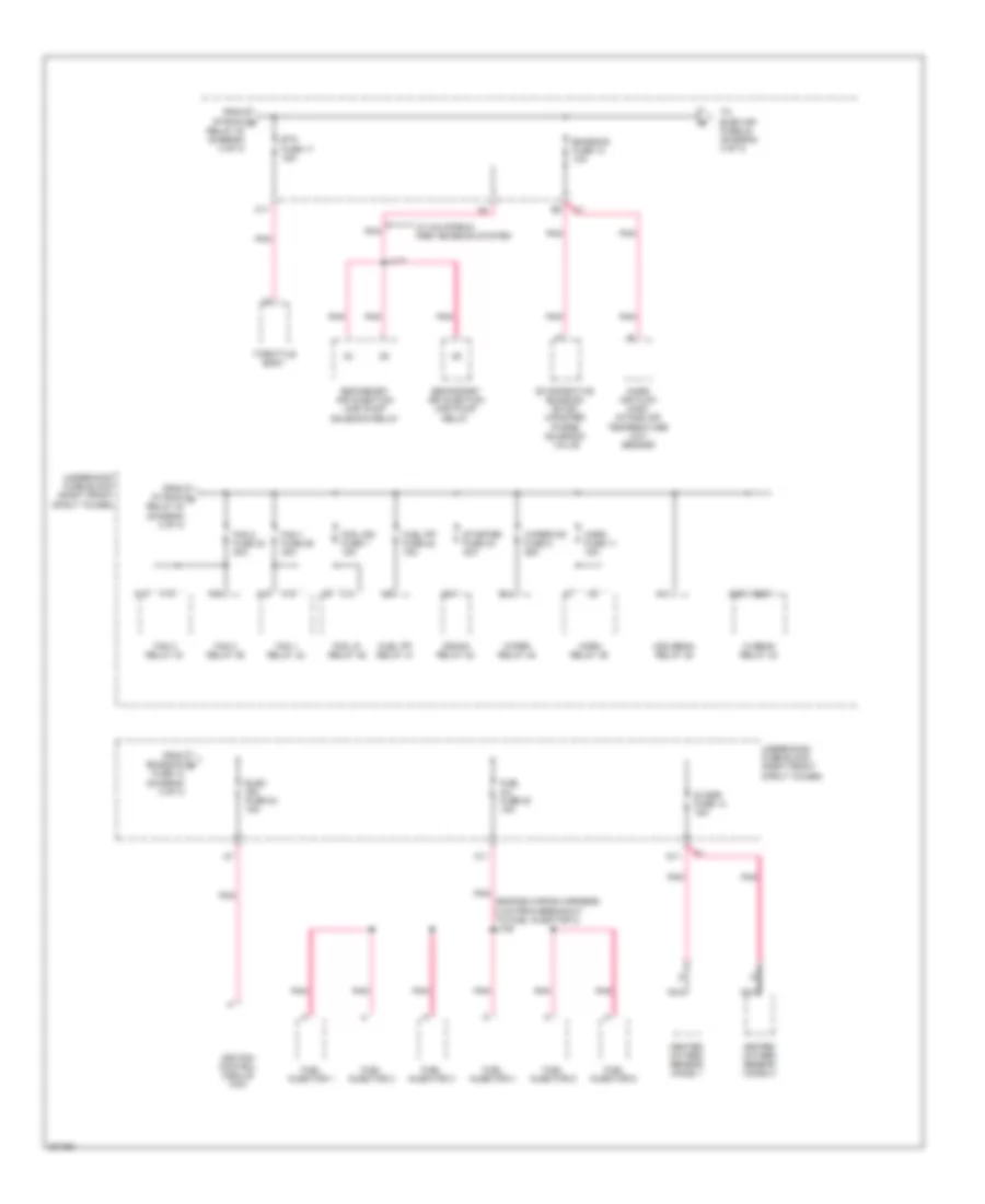
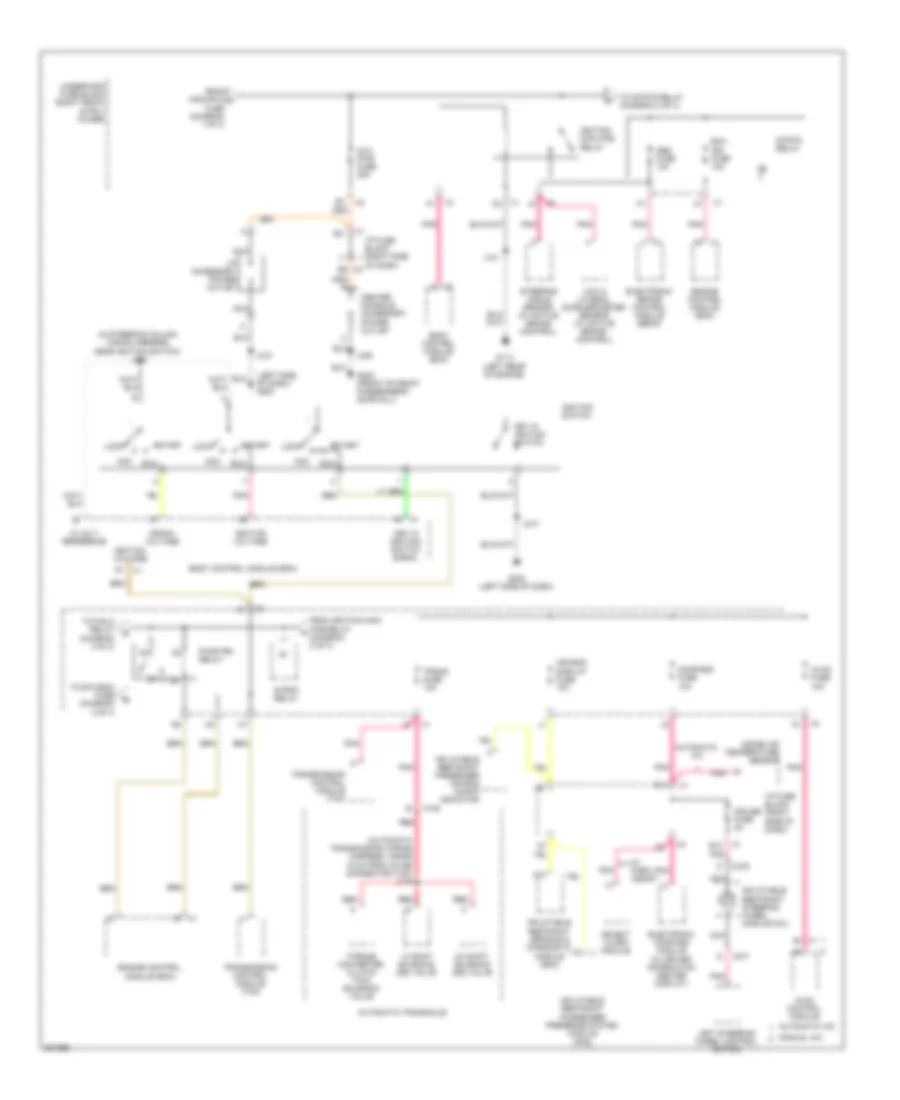
3.8L VIN 2, Power Distribution Wiring Diagram (2 of 3) for Buick Allure CXL 2009
List of elements for 3.8L VIN 2, Power Distribution Wiring Diagram (2 of 3) for Buick Allure CXL 2009:
- (automatic transmission wiring harness, 19 cm from inline connector x100) j115
- (left side of dash) g200
- (steering column wiring harness, near ignition switch) j200
- 1-2 shift solenoid (ss) valve
- 12 volt reference
- 2-3 shift solenoid (ss) valve
- A/c clutch fuse 13 10a
- A/c comp relay 38
- A10
- A11
- A2 x1
- Abs fuse 23 10a
- Acc
- Automatic a/c
- Automatic transmission
- Aux pwr fuse 10 25a
- Body control module (bcm)
- Center console accessory power outlet
- Crank relay
- Crank voltage
- Cruise fuse 2a
- D11
- Display fuse 18 10a
- E12
- Electronic brake control module (ebcm)
- Electronic compass module (w/ driver information center display)
- F12
- From ign 1 relay 37 (diagram 2 of 3)
- From washer/rvc a fuse 6 (diagram 1 of 3)
- G113 (lower left rear of engine, near starter)
- G202 (left side of dash)
- G302 (front of front passenger's door sill)
- Hvac control module
- I/p accessory power outlet
- I/p fuse block (right side of dash)
- Ign 1 relay 37
- Ignition switch
- Ignition voltage
- Inflatable restraint front passenger presence system module (pps)
- Inflatable restraint passenger air bag on/off indicator
- Inflatable restraint sensing & diagnostic module (sdm)
- Inflatable restraint steering wheel module coil
- Inside air temperature sensor
- J101
- J213
- J214
- J406
- Key in ignition switch
- Key in ignition switch signal
- Left steering wheel control switch
- Lock
- Manual a/c
- Nca
- Object alarm module
- P/train relay 40
- Pcm fuse 15 10a
- Pnk
- Powertrain control module (pcm)
- Red
- Run
- Sir fuse 9 10a
- Start
- Steering angle sensor (w/ active brake control)
- To a/c clutch fuse (diagram 2 of 3)
- To etc fuse 17 (diagram 3 of 3)
- To fan 2 fuse 32 (diagram 3 of 3)
- Torque converter clutch (tcc) solenoid valve
- Trans sol fuse 21 10a
- Underhood fuse block (right front strut tower)
- W/ park assist
- X1 b3
- X1 b4
- X100
- X2 a12
- X2 b9
- X275
- X277
- Yaw & lateral acceleration sensor (w/ active brake control)
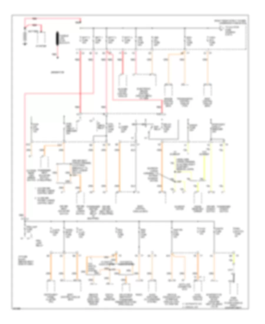
3.8L VIN 2, Power Distribution Wiring Diagram (3 of 3) for Buick Allure CXL 2009
List of elements for 3.8L VIN 2, Power Distribution Wiring Diagram (3 of 3) for Buick Allure CXL 2009:
- (engine wiring harness, 8 cm from breakout to fuel injector 3) j109
- 02 ssr fuse 14 15a
- A11
- A18
- A19
- C10
- C11
- Crank relay 48
- D11
- E14
- Elec ign fuse 24 15a
- Emission fuse 12 10a
- Etc fuse 17 15a
- Evaporative emission (evap) canister purge solenoid valve
- Fan 1 fuse 29 30a
- Fan 1 relay 42
- Fan 2 fuse 32 30a
- Fan 2 relay 46
- Fan 3 relay 43
- Fog lp relay 36
- Fog lps fuse 7 15a
- From emission e fuse 12 (diagram 3 of 3)
- From p/train b relay 40 (diagram 2 of 3)
- From p/train d relay 40 (diagram 2 of 3)
- Fuel inj fuse 20 15a
- Fuel injector 1
- Fuel injector 2
- Fuel injector 3
- Fuel injector 4
- Fuel injector 5
- Fuel injector 6
- Fuel pp fuse 22 15a
- Fuel pp relay 41
- G19
- G20
- Hdm beam relay 35
- Heated oxygen sensor (ho2s) 1
- Heated oxygen sensor (ho2s) 2
- Hi beam relay 34
- Horn fuse 11 15a
- Horn relay 39
- Ignition control module (icm)
- J117
- K15
- K18
- K19
- Mass air flow (maf)/ intake air temperature (iat) sensor
- Nca
- Pnk
- Secondary air injection (air) pump relay
- Secondary air injection (air) pump solenoid relay
- Starter fuse 33 40a
- Throttle body
- To elek ign fuse 24 (diagram 3 of 3)
- Underhood fuse block (right front strut tower)
- W/ california pzev emission system
- Wiper relay 45
- Wiper/ws fuse 5 25a
5.3L VIN C
5.3L VIN C, Power Distribution Wiring Diagram (1 of 3) for Buick Allure CXL 2009
List of elements for 5.3L VIN C, Power Distribution Wiring Diagram (1 of 3) for Buick Allure CXL 2009:
- (right front strut tower) underhood fuse block
- (sunroof wiring harness, 7.5 cm from sunroof motor)
- Abs mtr fuse 40a
- Abs sol fuse 25a
- Audio amplifier (w/ 9 speaker system)
- Automatic a/c
- B10
- Batt 1 fuse 50a
- Batt 2 fuse 50a
- Batt 3 fuse 40a
- Batt 4 fuse 30a
- Battery
- Blower motor control module
- Body control module (bcm)
- Chmsl/ bkup fuse 15a
- Clstr fuse 10a
- Cnstr fuse 10a
- D10
- Data link connector (dlc)
- Digital radio receiver
- Dr/lck trunk fuse 15a
- Driver heated seat relay (if equipped)
- Driver seat adjuster switch
- Driver seat lumbar switch
- Driver window switch
- E x2
- E12
- Ecm/ tcm fuse 15a
- Electronic brake control module (ebcm) (w/ abs)
- Engine control module (ecm)
- Evaporative emission (evap) canister vent solenoid valve
- F10
- Generator
- Hazrd fuse 20a
- Htd/ seat fuse 20a
- Hvac control module
- Hvac fuse 10a
- I/p fuse block (behind right side of dash)
- Inflatable restraint passenger presence system (pps) module
- Inside rearview mirror
- Instrument panel cluster (ipc)
- Int/ illum fuse 10a
- J331
- J395
- Manual a/c
- Nca
- Onstar/ aldl fuse 10a
- Outside rear- view mirror switch
- Park switch (floor console front compartment)
- Passenger heated seat relay (if equipped)
- Passenger seat adjuster switch (if equipped)
- Passenger window switch
- Power lumbar control seat
- Prk/ lamp relay
- Prk/ switch fuse 5a
- Prk/lamp fuse 10a
- Pwr/ mir fuse 10a
- Pwr/ seat circuit breaker 25a
- Pwr/wndw circuit breaker 25a
- R/ defog relay
- Radio
- Rap relay
- Rdo/ amp fuse 25a
- Red
- Remote control door lock receiver (rcdlr)
- Rfa/ mod fuse 10a
- S/roof fuse 20a
- Starter
- Sunroof motor
- To aux pwr fuse (diagram 2 of 3)
- Transmission control module (tcm)
- Vehicle communication interface module (vcim) (w/ onstar)
- W/ digital audio system
- W/ driver
- W/ sunroof
- W/o digital audio system
- W/o driver
- W/o sunroof
- Wsw/ rvc fuse 15a
- X1 a1
- X1 d12
- X2 e2
- X2 f9
- X2 g1
- X4 f1
5.3L VIN C, Power Distribution Wiring Diagram (2 of 3) for Buick Allure CXL 2009
List of elements for 5.3L VIN C, Power Distribution Wiring Diagram (2 of 3) for Buick Allure CXL 2009:
- (automatic transmission wiring harness, inside 19 cm from inline connector x100) j115
- (in steering column wiring harness, near ignition switch) j200
- (left side of dash) g200
- 1-2 shift solenoid (ss) valve
- 12 volt reference
- 2-3 shift solenoid (ss) valve
- A10
- A2 x1
- Abs fuse 10a
- Acc
- Air bag/ display fuse 10a
- Automatic a/c
- Automatic transaxle
- Aux pwr fuse 25a
- Body control module (bcm)
- Center console accessory power outlet
- Compass fuse 10a
- Crank voltage
- Cruise fuse 2a
- D11
- E12
- Ecm ign fuse 10a
- Electronic brake control module (ebcm)
- Electronic compass module (w/ driver information center display)
- Engine control module (ecm)
- From ignition main pcb relay (diagram 2 of 3)
- From wsw/rvc a fuse (diagram 1 of 3)
- G113 (left rear of engine)
- G202 (left side of dash)
- G302 (front of front passenger's door sill)
- Hvac control module
- Hvac fuse 10a
- I/p accessory power outlet
- I/p fuse block (right side of dash)
- Ignition main pcb relay
- Ignition switch
- Ignition voltage
- Inflatable restraint passenger air bag on/off indicator
- Inflatable restraint passenger presence system module (pps)
- Inflatable restraint sensing & diagnostic module (sdm)
- Inflatable restraint steering wheel module coil
- Inside air temperature sensor
- J101
- J213
- J214
- J406
- Key in ignition switch
- Key in ignition switch signal
- Left steering wheel control switch
- Lock
- Manual a/c
- Nca
- Object alarm module
- Pnk
- Pwr/trn relay
- Red
- Run
- Start
- Steering angle sensor (w/ active brake control)
- Strtr relay
- To etc/ecm fuse (diagram 3 of 3)
- To fan 2 relay (diagram 3 of 3)
- To strtr relay (diagram 2 of 3)
- Torque converter clutch (tcc) solenoid valve
- Trans fuse 10a
- Transmission control module (tcm)
- Underhood fuse block (right front strut tower)
- W/ park assist
- X1 c2
- X100
- X2 b9
- X275
- X277
- X4 h1
- Yaw & lateral accelerometer sensor (w/ active brake control)
5.3L VIN C, Power Distribution Wiring Diagram (3 of 3) for Buick Allure CXL 2009
List of elements for 5.3L VIN C, Power Distribution Wiring Diagram (3 of 3) for Buick Allure CXL 2009:
- (engine wiring harness, approx. 5 cm from breakout to fuel injector 4) j109
- (engine wiring harness, approximately 5 cm from fuel injector 3) j108
- (pre-engine wiring harness 5 cm from ignition coil 1) j106
- (right front strut tower) underhood fuse block
- A/c cmprsr relay
- Cylinder shutoff solenoid 1
- Cylinder shutoff solenoid 2
- Cylinder shutoff solenoid 3
- Cylinder shutoff solenoid 4
- Emissions 1 fuse 15a
- Emissions 2 fuse 15a
- Engine control module (ecm)
- Etc/ecm fuse 15a
- Evaporative emission (evap) canister purge solenoid valve
- Fan 1 fuse 30a
- Fan 1 relay
- Fan 2 fuse 30a
- Fan 2 relay
- Fan 3 relay
- Fog lps pcb relay
- From pwr/trn b relay (diagram 2 of 3)
- From pwr/trn d relay (diagram 2 of 3)
- Fuel injector
- Fuel/pump relay
- Hdm
- Heated oxygen sensor (ho2s) 1
- Heated oxygen sensor (ho2s) 2
- High beam pcb relay
- Horn pcb relay
- Ignition coil 1
- Ignition coil 2
- Ignition coil 3
- Ignition coil 4
- Ignition coil 5
- Ignition coil 6
- Ignition coil 8
- Ignition coil7
- Inj 1 fuse 20a
- Inj 2 fuse 20a
- J105 (ignition coil wiring harness, approximately 6 cm from x107)
- Mass air flow (maf)/ intake air temperature (iat) sensor
- Nca
- Pnk
- Valve lifter oil manifold (vlom) assembly
- Wiper pcb relay
- Wpr fuse 25a