POWER DISTRIBUTION
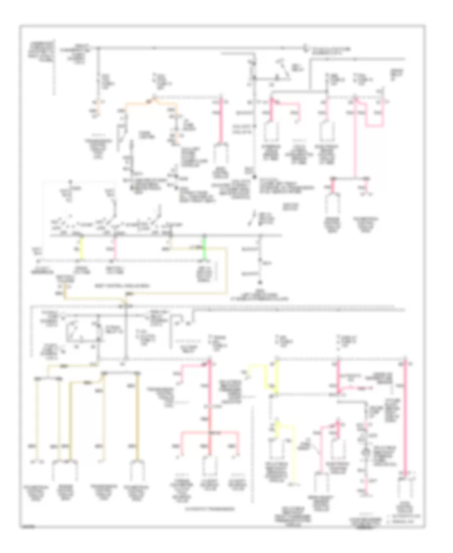
Power Distribution Wiring Diagram (1 of 4) for Buick LaCrosse CX 2005

List of elements for Power Distribution Wiring Diagram (1 of 4) for Buick LaCrosse CX 2005:
- (below driver seat, 36 cm from c311) s331
- (in headliner harn, at right front of headliner) s394
- (mounted to right strut tower) underhood fuse block
- 3.6l
- 3.8l
- A1 c1
- Abs mtr fuse 31 40a
- Abs sol fuse 19 25a
- Air pump fuse 25 50a
- Audio amplifier (w/ 9 speaker system)
- Automatic a/c
- B10
- Batt main 1 fuse 26 40a
- Batt main 2 fuse 27 50a
- Batt main 3 fuse 28 40a
- Batt main 4 fuse 30 30a
- Battery
- Blower motor control processor
- Body control module (bcm)
- C1 b1
- C1 d12
- C10
- C2 d9
- C2 e2
- C2 f9
- C4 c2
- Canister fuse 10a
- Chmsl/ bkup fuse 15a
- Clstr fuse 10a
- D10
- Data link connector (dlc)
- Digital radio receiver
- Dr/lck trunk fuse 15a
- Driver heated seat relay
- Driver seat adjuster switch
- Driver seat lumbar switch
- Driver window switch
- E c1
- E c2
- E12
- Electronic brake control module (ebcm) (w/ abs)
- Engine control module (ecm)
- Evaporative emission (evap) canister vent solenoid
- F10
- Front passenger window switch
- Generator
- Htd/ seat fuse 20a
- Hvac control module
- Hvac fuse 10a
- I/p fuse block (behind right side of dash)
- Inflatable restraint front passenger presence system (pps) module
- Inside rearview mirror
- Instrument panel cluster (ipc)
- Int illum fuse 10a
- Manual a/c
- Onstar/ aldl fuse 10a
- Outside rear view mirror switch
- Park switch
- Passenger front heated seat relay
- Passenger seat adjuster switch
- Pcm/ etc fuse 16 15a
- Power lumbar control seat
- Powertrain control module (pcm)
- Prk/ lamp relay
- Prk/ switch fuse 5a
- Prk/lamp fuse 10a
- Pwr wndw circuit breaker 25a
- Pwr/ mir fuse 10a
- Pwr/ seat circuit breaker 25a
- R/ defog relay
- Radio
- Rap relay
- Rdo amp fuse 25a
- Red
- Remote control door lock receiver (rcdlr)
- Rfa/ mod fuse 10a
- S/roof fuse 20a
- S395
- Secondary air injection (air) pump relay (sulev)
- Starter
- Sunroof motor/ actuator
- To aux pwr fuse 10 (diagram 2 of 4)
- Turn/ hazrd fuse 20a
- Vehicle communication interface module (vcim)
- W/ digital audio system
- W/ driver
- W/ sunroof
- W/o digital audio system
- W/o driver
- W/o sunroof
- Washer/ rvc fuse 6 15a
Power Distribution Wiring Diagram (2 of 4) for Buick LaCrosse CX 2005
List of elements for Power Distribution Wiring Diagram (2 of 4) for Buick LaCrosse CX 2005:
- (3.6l) g115 (mounted to bank 1 cylinder head, above exhaust manifold)
- (3.6l) s116
- (3.8l) s101
- (center of dash cross beam, behind radio) g200
- 1-2 shift solenoid valve
- 12 volt reference
- 2-3 shift solenoid valve
- 3.6l
- 3.8l
- A/c clutch fuse 13 10a
- A/c comp relay
- A10
- A11
- A2 c1
- Abs fuse 23 10a
- Acc
- Acc lock
- Automatic a/c
- Automatic transmission
- Aux pwr fuse 10 25a
- Aux tcm fuse 8 10a
- Auxiliary power outlet (under floor console)
- Body control module
- Body control module (bcm)
- C1 a5
- C1 b3
- C1 b4
- C1 d1
- C100
- C2 a12
- C2 b9
- C275
- C277
- Cigar lighter
- Crank relay
- Crank voltage
- Cruise fuse 2a
- D11
- Display fuse 18 10a
- E12
- Electronic brake control module (w/ abs)
- Electronic compass module
- Engine control module (ecm)
- F12
- From ign 1 relay (diagram 2 of 4)
- From washer/rvc a fuse 6 (diagram 1 of 4)
- G113 (3.8l) (lower left front of engine, on transmission stud, near starter)
- G202 (left side of dash, at base of steering column)
- G302 (in right door sill, forward of right front seat)
- Hvac control module
- I/p fuse block
- I/p fuse block (behind right side of dash)
- Ign 1 relay
- Ignition 1 voltage
- Ignition 3 voltage
- Ignition switch
- Inflatable restraint front passenger presence system module
- Inflatable restraint passenger airbag on/off indicator
- Inflatable restraint sensing & diagnostic module
- Inflatable restraint steering wheel module coil
- Inside air temperature sensor
- Key in ignition switch
- Key in ignition switch signal
- Lock
- Manual a/c
- Nca
- Off
- P/train relay 40
- Pcm fuse 15 10a
- Pnk
- Powertrain control module (pcm)
- Rear object sensor control module
- Red
- Run
- S115
- S213
- S214
- S406
- Sir fuse 9 10a
- Start
- Steering angle sensor (w/ abs)
- To a/c clutch fuse (diagram 2 of 4)
- To etc fuse 17 (diagram 3 of 4)
- To fan 2 fuse (diagram 3 of 4)
- Torque converter clutch (tcc) solenoid valve
- Trans sol fuse 21 10a
- Transmission control module (tcm)
- Transmission control module (tcm) (3.6l)
- Underhood fuse block (mounted to right strut tower)
- Voice recorder/ cruise switch assembly
- W/ park assist
- Yaw & lateral acceleration sensor (w/ abs)
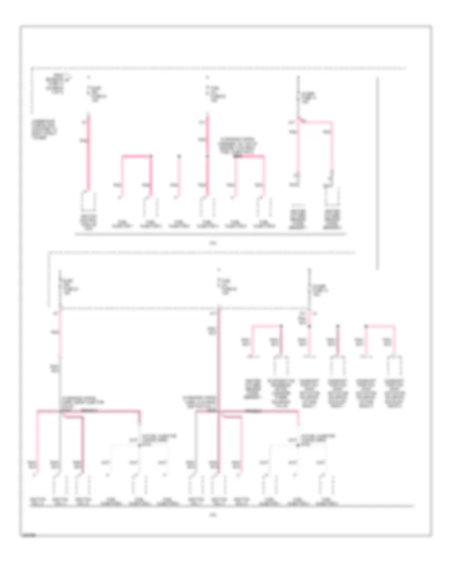
Power Distribution Wiring Diagram (3 of 4) for Buick LaCrosse CX 2005
List of elements for Power Distribution Wiring Diagram (3 of 4) for Buick LaCrosse CX 2005:
- (engine harness, 5cm pnk from secondary air injection (air) pump relay breakout, toward c100) s117
- 3.6l
- 3.8l
- A12
- A18
- A19
- C10
- C11
- Crank relay 48
- E14
- Emission fuse 12 10a
- Engine control module (ecm)
- Etc fuse 17 15a
- Evaporative emission (evap) canister purge solenoid
- Fan 1 fuse 29 30a
- Fan 1 relay 42
- Fan 2 fuse 32 30a
- Fan 2 relay 46
- Fan 3 relay 43
- Fog lp relay 36
- Fog lps fuse 7 10a
- From p/train b relay 40 (diagram 2 of 4)
- From p/train d relay 40 (diagram 2 of 4)
- Fuel pp fuse 22 15a
- Fuel pp relay 41
- G19
- G20
- Headlamp module
- Heated oxygen sensor (ho2s) 2
- Hi beam relay 34
- Horn fuse 11 15a
- Horn relay 39
- K15
- K18
- K19
- Mass air flow (maf) sensor/ intake air temperature (iat)
- Pnk
- Secondary air injection (air) pump relay
- Secondary air injection (air) solenoid relay
- Starter fuse 33 40a
- Sulev
- Throttle actuator control (tac) module
- To elek fuse 24 (diagram 4 of 4)
- Underhood fuse block (mounted to right strut tower)
- Wiper relay 45
- Wiper/ws fuse 5 25a
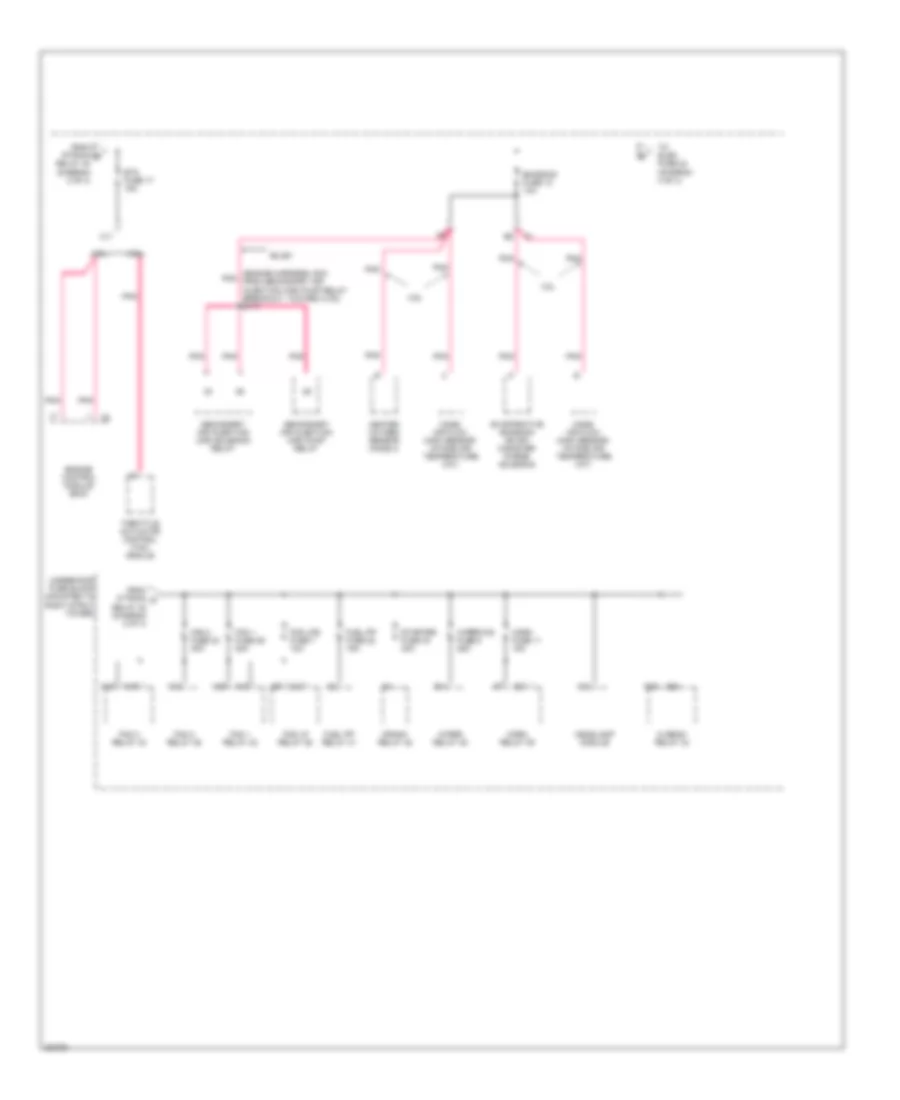
Power Distribution Wiring Diagram (4 of 4) for Buick LaCrosse CX 2005
List of elements for Power Distribution Wiring Diagram (4 of 4) for Buick LaCrosse CX 2005:
- (in engine wiring harn, 5 cm from ignition coil 1) s106
- (in engine wiring harn, near injector coils) s103
- (in engine wiring harness, on top of engine, 8 cm from fuel injector 3) s109
- (in fuel injector wiring harn) s104
- (in fuel injector wiring harn) s108
- 02 ssr fuse 14 15a
- 3.6l
- 3.8l
- A11
- Camshaft position (cmp) actuator solenoid exhaust bank 1
- Camshaft position (cmp) actuator solenoid exhaust bank 2
- Camshaft position (cmp) actuator solenoid intake bank 1
- Camshaft position (cmp) actuator solenoid intake bank 2
- D11
- Elek ign fuse 24 15a
- Evaporative emissions (evap) canister purge solenoid valve
- From emission e fuse 12 (diagram 3 of 4)
- Fuel inj fuse 20 15a
- Fuel injector 1
- Fuel injector 2
- Fuel injector 3
- Fuel injector 4
- Fuel injector 5
- Fuel injector 6
- Heated oxygen sensor (ho2s) sensor 1
- Heated oxygen sensor (ho2s) sensor 2
- Ignition coil 1
- Ignition coil 2
- Ignition coil 3
- Ignition coil 4
- Ignition coil 5
- Ignition coil 6
- Ignition control module (icm)
- Nca
- Pnk
- Underhood fuse block (mounted to right strut tower)