POWER DISTRIBUTION
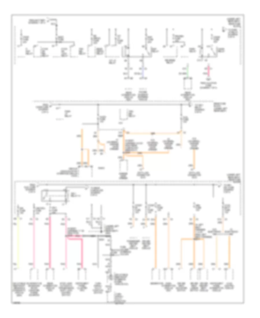
Power Distribution Wiring Diagram (1 of 4) for Buick LeSabre Limited 2004

List of elements for Power Distribution Wiring Diagram (1 of 4) for Buick LeSabre Limited 2004:
- (right front side of engine compartment) underhood fuse block
- A/c clu fuse 15a
- A/c clu relay
- A10
- Abs fuse 50a
- Accy fuse 15a
- Accy relay
- Automatic trans- mission
- Aux pwr fuse 20a
- B12
- Battery
- C/ltr fuse 20a
- Cigar lighter
- Cool fan 1 (low speed relay)
- Cool fan 1 fuse 30a
- Cool fan 2 (high speed relay)
- Cool fan 2 fuse 30a
- Cool fan s/p relay
- Cr cont fuse 10a
- Cruise control module (ccm)
- D12
- Dis fuse 20a
- Drl relay
- E12
- Electronic brake control module
- Evaporative emissions (evap) canister purge solenoid
- Fog/ drl fuse 15a
- From fog/ b drl fuse (diagram 1 of 4)
- From pcm c batt fuse (diagram 1 of 4)
- Front auxiliary power outlet
- Fuel injector
- G10
- G103 (on inner body panel)
- G11
- G201 (on right front door pillar)
- G301 (on forward crossmember)
- Generator
- Hdlp lo bm relay
- Hdlp hi bm relay
- Heated oxygen sensor bank 1 sensor 1 (ho2s1)
- Heated oxygen sensor bank 1 sensor 2 (ho2s2)
- Horn fuse 15a
- Horn relay
- Ign 1 fuse 10a
- Ign-1 relay 38
- Ignition control module (icm)
- Injr 1 fuse 10a
- Injr 2 fuse 10a
- Interior lights system
- M10
- M11
- Mass air flow (maf) sensor
- Outside moisture sensor
- Oxy sen fuse 10a
- Pcm batt fuse 10a
- Pcm ign fuse 10a
- Pnk
- Pnk p
- Power- train control module
- Powertrain control module (pcm)
- Q10
- Rear auxiliary power outlet
- Red
- S10
- S203
- S350
- Sp103
- Sp201
- Sp301 (in body harness, 8.5 cm from g300 breakout)
- Start 1 relay
- Start circuit breaker 30a
- Start relay
- Starter solenoid
- Theft deterrent control module
- To cigar relay (diagram 2 of 4)
- To hdlp lo bm relay (diagram 1 of 4)
- To ign-1 relay (diagram 1 of 4)
- To rear fuse block (diagram 2 of 4)
- To underhood fuse block (diagram 4 of 4)
- Trans fuse 10a
- Underhood fuse block (right front side of engine compt)
- V10
- W/ battery saver
- W/o battery saver
- Wind- shield wiper motor
- Wind- shield wiper switch
- Wsw fuse 30a
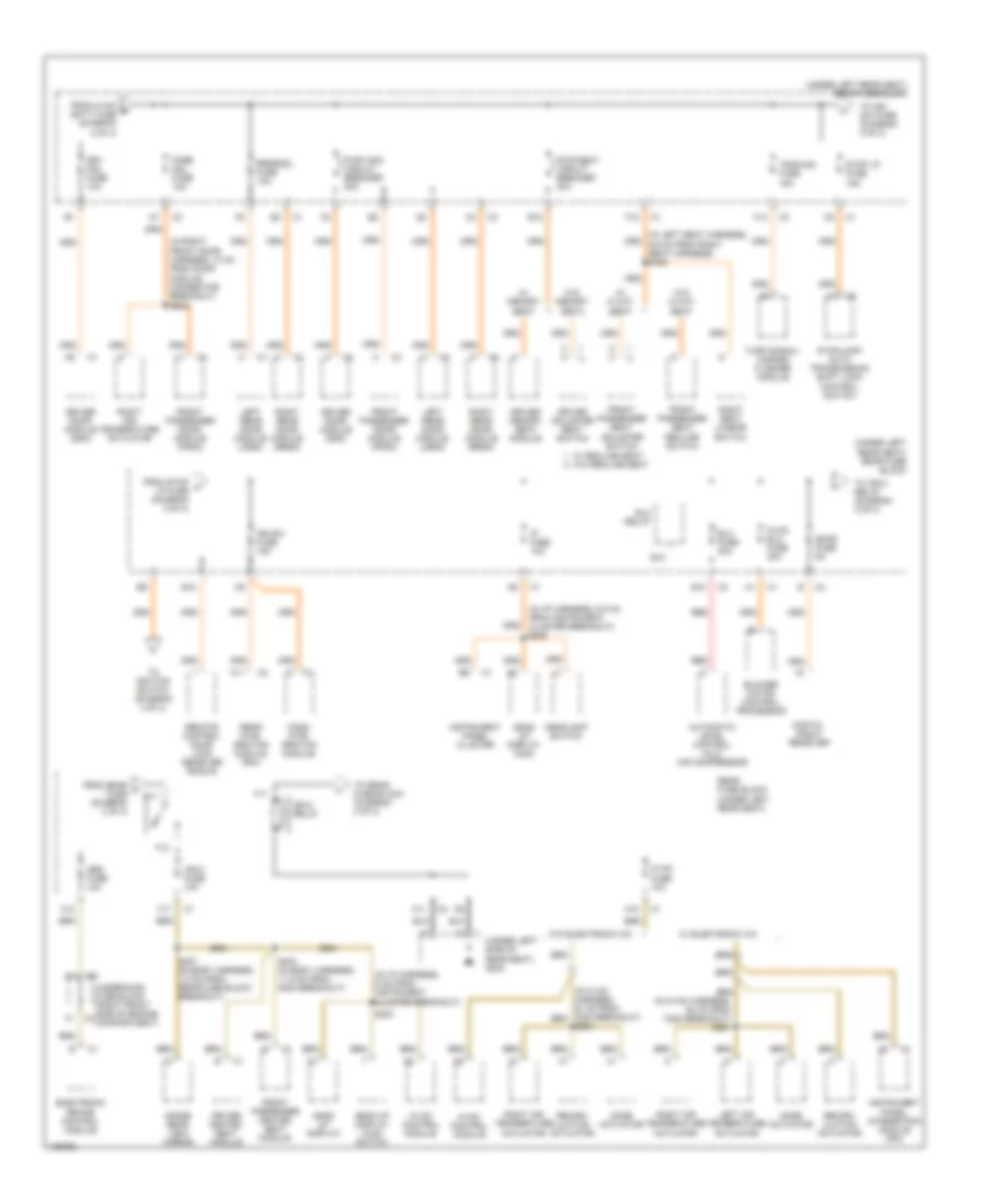
Power Distribution Wiring Diagram (2 of 4) for Buick LeSabre Limited 2004
List of elements for Power Distribution Wiring Diagram (2 of 4) for Buick LeSabre Limited 2004:
- (in body harness, 17 cm from p100) s216
- (in body harness, 5.5 cm from rear fuse block breakout) s308
- (under left rear seat) rear fuse block
- (under left side of rear seat) g302
- A10
- A11
- A12
- Aldl fuse 10a
- Audio fuse 10a
- B nca
- B12
- Body fuse 15a
- C10
- C2 c4
- Cigar fuse 40a
- Cigar relay
- D10
- D11
- D12
- Dash integration module (dim)
- Data link connector (dlc)
- Dim fuse 10a
- Driver heated seat module
- Driver memory seat module
- Driver seat adjuster switch
- Driver seat lumbar switch
- E11
- Evaporative emissions (evap) canister purge solenoid
- F/ pmp relay
- F/pmp fuse 20a
- F/tnk dr lock relay
- F/tnk dr rel relay
- From aux/pwr fuse (diagram 1 of 4)
- From battery a (diagram 1 of 4)
- From e cigar fuse (diagram 2 of 4)
- From f aldl fuse (diagram 2 of 4)
- Fuse holder steering column
- Garage door opener
- Generator
- Htdst lf fuse 10a
- Htdst rf fuse 10a
- Hvac batt fuse 10a
- Hvac control module
- Ign-1 fuse 10a
- Ign-1 relay 41
- Inflatable restraint sensing & diagnostic module (sdm)
- Inflatable restraint steering wheel module coil
- Instrument panel cluster (ipc)
- Instrument panel integration module
- Int lp fuse 10a
- Int lp relay
- L10
- L11
- L12
- Mem fuse 10a
- N10
- Nca
- Park lp relay
- Park relay
- Passenger heated seat module
- Pnk
- Power sunroof express module
- Prk/rev fuse 10a
- Radio
- Rap fuse 20a
- Rap relay
- Rear defog relay
- Rear fuse block (under left rear seat)
- Rear integration module (rim)
- Reverse relay
- Rr defog fuse 40a
- S224
- Sir fuse 15a
- Stop lamp/ automatic transmission shift lock control switch
- Switch fuse 2a
- To drv mdl fuse (diagram 3 of 4)
- To ign-1 relay (diagram 2 of 4)
- To park lp relay (diagram 2 of 4)
- To rear fuse block (diagram 4 of 4)
- Trk rel relay
- Trk/ rel relay
- Turn signal/ multi- function switch
- Vehicle communication interface module (vcim)
- Ventsol fuse 10a
- W/ electronic a/c
- W/ universal garage door opener
- W/o electronic a/c
- W/o universal garage door opener
Power Distribution Wiring Diagram (3 of 4) for Buick LeSabre Limited 2004
List of elements for Power Distribution Wiring Diagram (3 of 4) for Buick LeSabre Limited 2004:
- (in i/p harness, 6 cm from instrument cluster breakout)
- (in i/p harness, 6.5 cm from instrument cluster breakout) s206
- (in left seat harness, 9.5 cm from right seat harness) s323
- (in right front door harness, 10 cm from door module connector breakout) s602
- (under left rear seat) rear fuse block
- (under left side of rear seat) g302
- A h
- A10
- A11
- Abs fuse 10a
- Automatic level control (alc) air compressor
- B10
- Blower motor control processor
- C11
- C12
- Dash inte- gration module
- Digital radio receiver
- Driver adjuster seat switch
- Driver door module (ddm)
- Driver heated seat module
- Driver memory seat module
- Drv mdl fuse 10a
- E10
- E12
- Elc fuse 30a
- Elc relay
- Electronic brake control module
- F h
- F1 c3
- F11
- F12
- From hvac g batt fuse (diagram 2 of 4)
- From sdar i fuse (diagram 3 of 4)
- From stop h lp fuse (diagram 3 of 4)
- Front passenger door module (fpdm)
- Front passenger heated seat module
- Front passenger seat adjuster switch
- Front passenger seat recline switch
- H11
- Head up display
- Head up display (hud)
- Head up display (hud) switch
- Headlamp switch
- Hvac blo fuse 30a
- Hvac control module
- Hvac fuse 10a
- Ign sw fuse 15a
- Ign-3 fuse 10a
- Ign-3 relay
- Inside rear view mirror
- Instrument panel cluster
- Instrument panel integration module (ipm)
- Ip fuse 10a
- Left air temperature actuator
- Left rear door module (lrdm)
- Mode actuator
- Pass mdl fuse 10a
- Pwr seat circuit breaker 30a
- Pwr wdo circuit breaker 30a
- Rear fuse block (under left rear seat)
- Rear inte- gration module (rim)
- Recirc- ulation actuator
- Red
- Remote control door lock receiver (rcdlr)
- Right air temperature actuator
- Right rear door module (rrdm)
- Right seat lumbar switch
- Rrdrmdl fuse 10a
- S200
- S221
- S304 (in body harness, 11.5 cm from g300 breakout)
- S307 (in body harness, 1.5 cm from rear fuse block breakout)
- Sdar fuse 5a
- Stop lp fuse 15a
- Stoplamp/ auto transmission shift lock control switch
- To ign sw fuse (diagram 3 of 4)
- To ign-3 relay (diagram 3 of 4)
- To ignition switch (diagram 4 of 4)
- To rear fuse block (diagram 4 of 4)
- Tsig/haz fuse 15a
- Turn signal/ hazard flasher module
- Underhood fuse block (right front side of engine compartment)
- W/ 6 way seat
- W/ electronic a/c
- W/ memory seat
- W/ recline seat w/o recline seat
- W/o 6 way seat
- W/o electronic a/c
- W/o memory seat
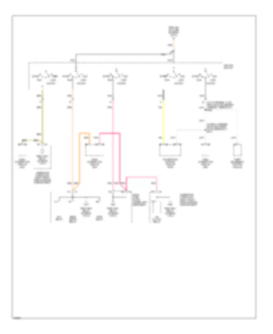
Power Distribution Wiring Diagram (4 of 4) for Buick LeSabre Limited 2004
List of elements for Power Distribution Wiring Diagram (4 of 4) for Buick LeSabre Limited 2004:
- (in body harness, 56 cm from rear of dim breakout) s212
- (in i/p harness, 13 cm from sunload sensor assembly breakout) s208
- A/c clutch relay
- A11
- Acc
- Dash integration module (dim)
- E10
- Elc relay
- From accy relay (diagram 1 of 4)
- From ign sw fuse (diagram 3 of 4)
- From ign-1 relay (diagram 1 of 4)
- From ign-1 relay (diagram 2 of 4)
- From ign-3 relay (diagram 3 of 4)
- Ignition switch
- Lock
- Nca
- Park relay
- Pnk
- Powertrain control module (pcm)
- Rear defog relay
- Rear fuse block (under left rear seat)
- Run
- Start
- T10
- Theft deterrent control module
- Underhood fuse block (right front side of engine compartment)
- Unlock
- V11