POWER DISTRIBUTION
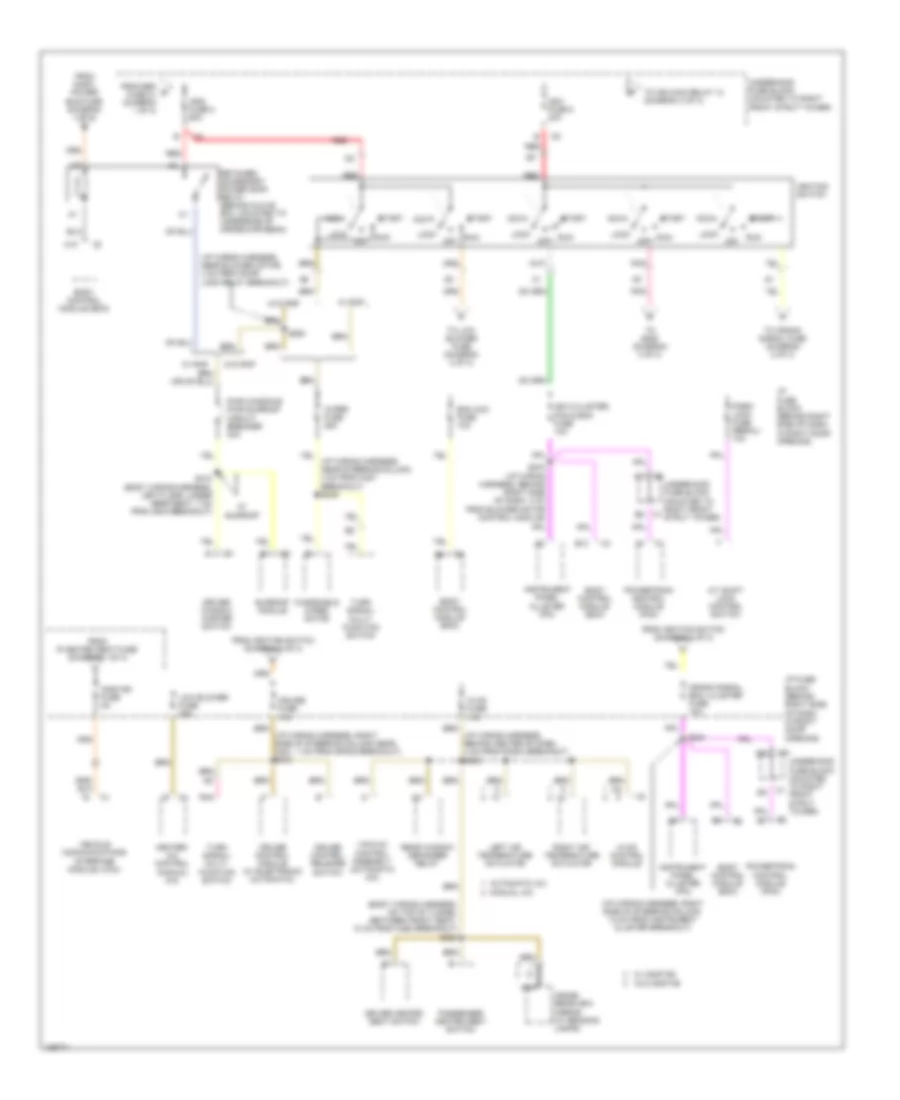
Power Distribution Wiring Diagram (1 of 3) for Buick Regal GS 2004

List of elements for Power Distribution Wiring Diagram (1 of 3) for Buick Regal GS 2004:
- (body wiring harness, below right front seat, 60 cm from c312 breakout) s326
- (body wiring harness, in rear compt, 6.5 cm from right rear radio speaker breakout) s440
- (i/p wiring harness, right side of steering column, 19 cm from radio breakout) s202
- (regal)
- 60a
- A/c clutch fuse 23 10a
- A/c clutch relay 15
- Abs fuse 1
- Accy pwr bus fuse 15a
- Audio amplifier (w/ premium radio)
- Automatic a/c
- Automatic headlamp relay
- Auxiliary power outlet (in floor console)
- Back-up lamp relay
- Batt 1 fuse 7 60a
- Batt 2 fuse 4 60a
- Batt 3 fuse 3 60a
- Battery
- Bcm pwr fuse 10a
- Blower motor control processor
- Blower motor resistor assembly
- Body control module (bcm)
- C2 l c12
- Cigar lighter
- Cool fan 1 fuse 6 25a
- Cool fan 1 relay 12
- Cool fan 2 fuse 24 15a
- Cool fan 2 relay 9
- Cool fan 3 relay 10
- Crank fuse 2 40a
- Crank relay 11
- Data link connector (dlc)
- Door locks fuse 20a
- Driver heated seat control module
- Driver seat adjuster switch
- E10
- E11
- E12
- Ecm fuse 22 10a
- Electronic brake control module (ebcm)
- F/pmp fuse 35 15a
- F/pmp relay 19
- F/pmp spd cont relay 18 (3.8l (vin 1) w/ front fog lamp)
- Fog lamp relay 17
- Fog lp fuse 31 10a (regal)
- From batt 2 fuse 4 (diagram 1 of 3)
- From f/pmp a fuse 35 (diagram 1 of 3)
- Front passenger heated seat control module
- Front passenger seat adjuster switch
- Fusible link (10 ga- rust)
- G200 (behind right side of dash compt)
- Gen fuse 21 10a
- Generator
- Hazard fuse 15a
- Hdlp l fuse 36 15a
- Hdlp r fuse 32 15a
- Headlamp switch
- High blower fuse 30a
- Horn fuse 27 15a
- Horn relay 16
- Hvac control module
- I/p fuse block (behind right side of dash, in right door opening)
- I/p fuse block (behind right side of dash, in right door opening)
- Instrument panel cluster (ipc)
- L heated seat fuse 15a (regal)
- Left headlamp assembly
- Left high beam headlamp
- Left low beam headlamp
- Lp park fuse 34 20a
- Ltr fuse 20a
- M10
- Manual a/c
- Nca
- Outside rearview mirror switch
- Park lamp relay
- Power mirrors fuse 2a
- Power seat circuit breaker 30a
- Powertrain control module (pcm)
- R heated seat fuse 15a (regal)
- R/cmpt rel fuse 33 7.5a
- R10
- R11
- Radio
- Radio prem sound fuse 15a
- Radio,hvac rfa,cluster aldl fuse 15a
- Rear compartment lid release relay
- Rear defog circuit breaker 30a
- Rear window defogger relay
- Red
- Red a
- Regal
- Remote control door lock receiver (rcdlr)
- Right headlamp assembly
- Right high beam headlamp
- Right low beam headlamp
- S230
- S269 (i/p wiring harness, near blower motor, 13 cm from door lock relay breakout)
- S275
- S335
- Starter
- Stop lamps fuse 15a
- Stoplamp switch
- T10
- To hdlp l fuse 36 (diagram 1 of 3)
- To high blower fuse (diagram 1 of 3)
- To ign 2 fuse 8 (diagram 2 of 3)
- To onstar fuse, diagram (2 of 3)
- To retained accessory power (rap) relay (diagram 2 of 3)
- Turn signal/ hazard flasher module
- Underhood fuse block (mounted to right front strut tower)
- W/ passenger power seat
- W/ rap
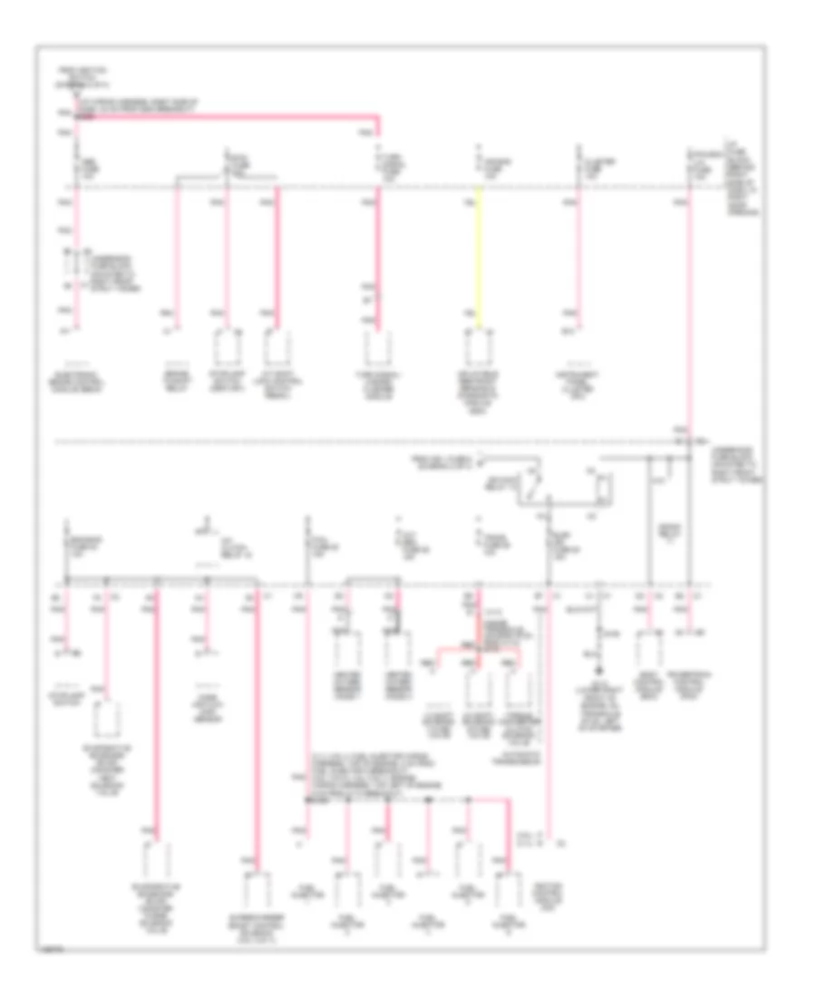
Power Distribution Wiring Diagram (2 of 3) for Buick Regal GS 2004
List of elements for Power Distribution Wiring Diagram (2 of 3) for Buick Regal GS 2004:
- (body wiring harness, on top of tunnel between front seat, 10 cm from c250 breakout) s323
- (i/p wiring harness, behind center of dash, 4 cm from radio breakout) s233
- (i/p wiring harness, near blower motor, 4 cm from door lock relay breakout)
- (i/p wiring harness, right side of steering column near, c201, 1 cm from sp205 breakout) s240
- (i/p wiring harness, right side of steering column, 13 cm from instrument cluster breakout)
- A/t shift lock control switch
- A10
- Acc
- Automatic a/c
- B10
- Bcm acc fuse 10a
- Body control module (bcm)
- C5 c
- Crank signal, bcm, cluster fuse 10a
- Cruise control module (w/ electronic automatic)
- Cruise control release switch
- Cruise fuse 10a
- Driver heated seat switch
- Driver window master switch
- From gen d fuse 21 (diagram 1 of 3)
- From ignition switch (diagram 2 of 3)
- From inadv power bus fuse (diagram 1 of 3)
- From r heated seat fuse (diagram 1 of 3)
- Heater- a/c control (manual a/c)
- Hvac control module
- Hvac fuse 10a
- I/p fuse block (behind right side of dash, in right door opening)
- Ign 0,cluster, pcm & bcm fuse 10a
- Ign1 fuse 5 30a
- Ign2 fuse 8 60a
- Ignition switch
- Inside rearview mirror (w/ reading lamps)
- Instrument panel cluster (ipc)
- Left air temperature actuator
- Lock
- Low blower fuse 20a
- Manual a/c
- Nca
- Off
- Onstar fuse 5a
- Park/ lock fuse (regal) 10a
- Passenger heated seat switch
- Pnk
- Powertrain control module (pcm)
- Pwr windows pwr sunroof circuit breaker 30a
- Rear window defogger relay
- Red
- Retained accessory power (rap) relay (behind glove box, mounted to underside of cross-car beam)
- Right air temperature actuator
- Run
- S234
- S263
- S270 (i/p wiring harness, behind right side of dash, 4 cm from blower motor control module)
- S410 (body wiring harness, left floor, under rear seat, 7 cm from c405 breakout)
- Start
- Sunroof module
- To crank signal fuse (diagram 2 of 3)
- To ign main relay 13 (diagram 3 of 3)
- To low blower fuse (diagram 2 of 3)
- To s228 (diagram 3 of 3)
- Turn signal/ multi- function switch
- Underhood fuse block (mounted to right front strut tower)
- Vacuum control assembly (automatic a/c)
- Vehicle communications interface module (vcim)
- W/ onstar
- W/ rap
- W/ sunroof
- W/o onstar
- W/o rap
- Windshield wiper motor
- Wiper fuse 25a
Power Distribution Wiring Diagram (3 of 3) for Buick Regal GS 2004
List of elements for Power Distribution Wiring Diagram (3 of 3) for Buick Regal GS 2004:
- (3.1l (vin j): fuel injector wiring harness, top of engine, 2 cm from fuel injector 2 breakout) (3.8l (vin k), 3.8l (vin 1): engine wiring harness, top left of engine, 6 cm from c110 breakout) s109
- (3.1l)
- (3.8l)
- (i/p wiring harness, right side of dash, 24 cm from g200 breakout) s228
- (inside transaxle housing,19 cm from c113) s115
- 1-2 shift solenoid (1-2 ss) valve
- 2-3 shift solenoid (2-3 ss) valve
- A/c clutch relay 15
- A/t shift lock control switch (regal)
- A11
- Abs fuse 10a
- Air bag fuse 10a
- Automatic transmission
- B12
- Body control module (bcm)
- Brake- to-shift relay
- Btsi fuse 10a
- C113
- Cluster fuse 10a
- Crank relay
- Electronic brake control module (ebcm)
- Elek ign fuse 25 15a
- Eng emis fuse 30 10a
- Evaporative emissions (evap) canister purge solenoid valve
- Evaporative emissions (evap) canister vent solenoid valve
- F/inj fuse 28 15a
- From ign 1 fuse 5 e (diagram 2 of 3)
- From ignition switch (diagram 2 of 3)
- Front of engine, on transaxle stud, left of starter)
- Fuel injector
- G113 (lower right
- Heated oxygen sensor (ho2s) 1
- Heated oxygen sensor (ho2s) 2
- I/p fuse block (behind right side of dash, in right door opening)
- Ign main relay 13
- Ignition control module (icm)
- Inflatable restraint sensing & diagnostic module (sdm)
- Instrument panel cluster (ipc)
- K10
- Mass air flow (maf) sensor
- Nca
- Oxy sen fuse 29 15a
- Pcm,bcm u/h fuse 10a
- Pnk
- Powertrain control module (pcm)
- Red
- S106
- Stoplamp switch
- Stoplamp switch (century)
- Supercharger boost control solenoid (3.8l (vin 1))
- Torque converter clutch solenoid valve
- Trans fuse 26 10a
- Turn signal fuse 10a
- Turn signal/ hazard flasher module
- Underhood fuse block (mounted to right front strut tower)