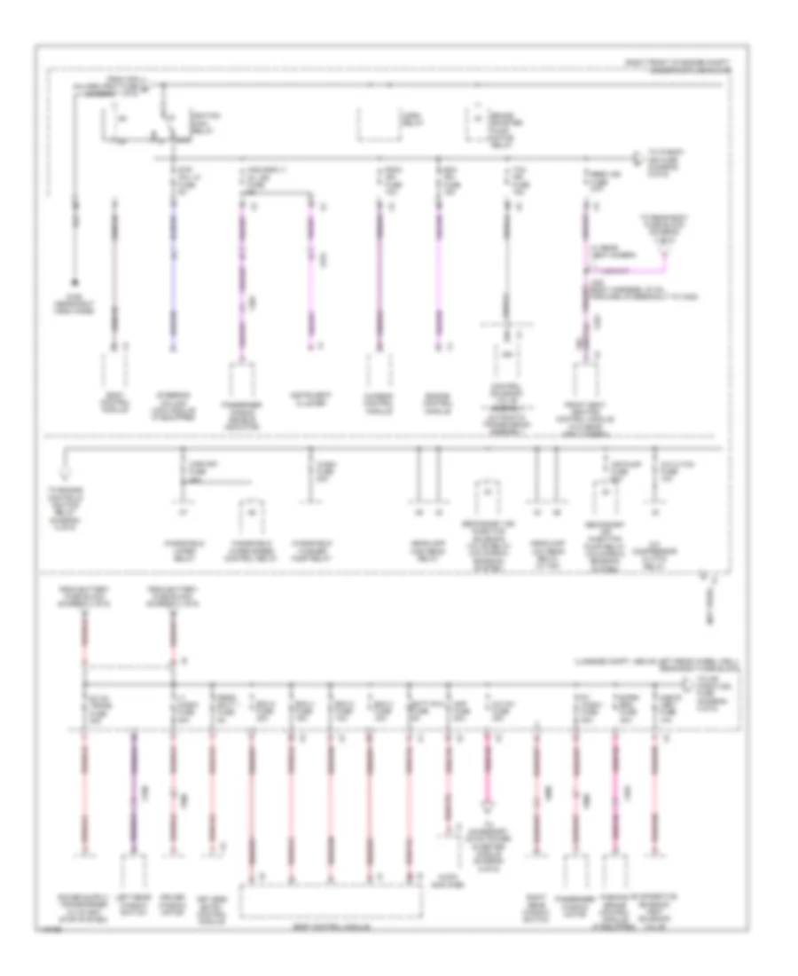
POWER DISTRIBUTION
Power Distribution Wiring Diagram (1 of 6) for Cadillac ATS Luxury 2014

List of elements for Power Distribution Wiring Diagram (1 of 6) for Cadillac ATS Luxury 2014:
- (not used)
- (on battery) battery fuse block
- (right front of engine compt) auxiliary underhood fuse block
- (right front of engine compt) underhood fuse block
- 5cm from hood ajar switch breakout)
- Abs pump fuse 60a
- Abs vlv fuse 30a
- Afs ahl/ ped prot fuse 10a
- Ahl fuse 10a
- Automatic transmission assembly
- Battery
- Battery fuse holder
- Battery sensor module
- Bcm 1/ spare fuse 10a
- Bcm 5 fuse 15a
- Bcm 6 fuse 10a
- Bcm 7 fuse 10a
- Body control module
- Control solenoid valve assembly
- Cool fan fuse 60a
- Cooling fan control module (if equipped)
- Cooling fan motor (if equipped)
- Driver seat adjuster switch
- Driver seat memory control module
- Drvr pwr seat fuse 30a
- Electronic brake control module
- Front seat heating control module (if equipped)
- Fuse 100a
- Fuse 200a
- Fuse 250a
- Fuse 300a
- Fuse 60a
- Fuse 70a
- Fuse holder 5a
- Fuse n/a
- Generator
- Headlamp control module (w/ hid)
- Ign
- Keyless entry control module
- Left headlamp assembly (w/ hid)
- Nca
- Pass pwr seat fuse 30a
- Pass wndw sw fuse 10a
- Passenger seat adjuster switch
- Passenger window switch (w/ memory)
- Pedestrian impact detection control module (if equipped)
- Peps fuse 30a
- Power steering control module
- Red
- Right headlamp assembly (w/ hid)
- S/roof fuse 30a
- Spare/ htd seat2 fuse 15a
- Starter motor
- Starter relay
- Strtr fuse 30a
- Sunroof motor (if equipped)
- Tcm/spare fuse 15a
- To ignition main relay (diagram 2 of 6)
- To instrument panel fuse block (diagram 4 of 6)
- To rear body fuse block (diagram 2 of 6)
- W/ memory
- W/o memory
- X109
- X275
- X321
- X322
- X338
- X600
- X606
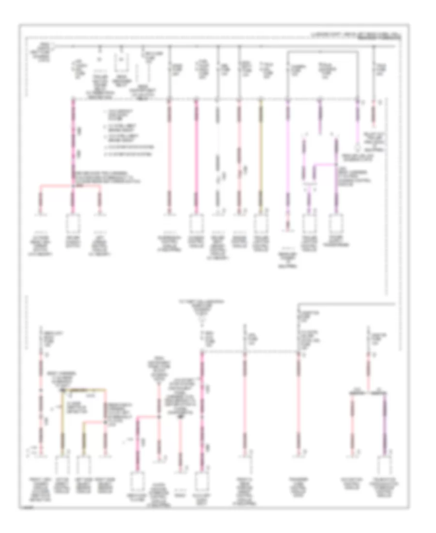
Power Distribution Wiring Diagram (2 of 6) for Cadillac ATS Luxury 2014
List of elements for Power Distribution Wiring Diagram (2 of 6) for Cadillac ATS Luxury 2014:
- (luggage compt, above left rear wheel well) rear body fuse block
- (not used)
- (right front of engine compt) underhood fuse block
- 87a
- A/c cltch fuse 10a
- A/c compressor clutch relay
- A/c inv fuse 30a
- Air pump fuse 50a
- Amp fuse 30a
- Aos disply/ mil ign fuse 5a
- Audio amplifier
- Automatic transmission assembly
- Batt rvc fuse 5a
- Bcm 2 fuse 10a
- Bcm 3 fuse 15a
- Bcm 4 fuse 15a
- Bcm 8 fuse 30a
- Body control module
- Brake booster pump motor relay
- Chassis control module
- Cnstr vent fuse 10a
- Control solenoid valve assembly
- Dc dc trans fuse 30a
- Driver window motor
- E/prk brk fuse 30a
- Ecm ign fuse 15a
- Engine control module
- Evaporative emission vent solenoid valve
- From afs ahl/ped prot fuse e (diagram 1 of 6)
- From battery fuse block (diagram 1 of 6)
- Front seat heating control module (w/o rear view camera)
- Fscm ign fuse 10a
- G106 (near right hood hinge)
- Headlamp high beam relay
- Headlamp low beam relay (w/ hid)
- Horn relay
- Ign
- Ignition main relay
- Instrument cluster
- J330 (body harness, 20 cm forward of breakout to x322)
- Keyless entry control module
- Left rear window switch
- Lt wndw fuse 30a
- Parking brake control module (if equipped)
- Passenger air bag disable indicator
- Passenger window motor
- Peps/ batt 1 fuse 5a
- Rbec ign fuse 20a
- Right rear window switch
- Rt wndw fuse 30a
- Secondary air injection pump relay (california emission system)
- Secondary air injection solenoid valve relay (california emission system)
- Steering column lock module (if equipped)
- Str col lk fuse 5a
- Tcm ign fuse 15a
- To accessory dc/ac power inverter module (diagram 6 of 6)
- To engine controls ignition relay (diagram 5 of 6)
- To ip body ign fuse (diagram 5 of 6)
- To mir wndw mdl fuse (diagram 3 of 6)
- To rear body fuse block (diagram 3 of 6)
- W/ rear view camera
- Wash fuse 20a
- Windshield washer pump relay
- Windshield wiper relay
- Windshield wiper speed control relay
- Wpr frt fuse 30a
- X275
- X301
- X322
- X403
- X500
- X600
- X700
- X800
Power Distribution Wiring Diagram (3 of 6) for Cadillac ATS Luxury 2014
List of elements for Power Distribution Wiring Diagram (3 of 6) for Cadillac ATS Luxury 2014:
- (body harness, 17 cm rear of branch to g401) j402
- (driver door trim harness, 6 cm forward of breakout to outside rearview mirror switch) j505
- (instrument panel harness, 9 cm from branch to center stack & tunnel components) j209
- (luggage compt, above left rear wheel well) rear body fuse block
- (rear fascia harness, 12.5 cm left of breakout to x416) j416
- Active safety control module
- Auxiliary audio input
- Brake assist
- Camera fuse 10a
- Chassis control module
- Disc & mp3 player
- Driver seat memory control module (w/ memory)
- Driver window switch
- Ecm/ batt fuse 10a
- Engine control module
- From cnstr j vent fuse (diagram 2 of 6)
- From instrument panel fuse block (diagram 4 of 6)
- From splice j330 (diagram 2 of 6)
- Front & rear parking assist control module (if equipped)
- Front view camera module (w/o side obstacle detection)
- Fuel pump fscm fuse 20a
- Human machine interface control module (if equipped)
- J403 (body harness, 31 cm from chassis control module)
- Left mirror control module (w/ memory)
- Left side object sensor module
- Logistics fuse 10a
- Media disc player
- Mir wndw mdl fuse 5a
- Msm fuse 10a
- Navigation control module
- Onstar fuse 10a
- Outside rear view mirror switch (w/o memory)
- Pnk
- Radio
- Rdo/ dvd fuse 15a
- Rear compartment lid unlatch relay
- Rear defogger relay
- Rearview camera (if equipped)
- Right side object sensor module
- Rr closr fuse 10a
- Sads fuse 25a
- Sbza/ldw/ eocm fuse 15a
- Suspension control module (if equipped)
- Tc cntrl mdl/rr cntrl mdl fuse 15a
- Telematics communication interface control module
- To theft mdl/ugdo/rain snsr fuse (diagram 6 of 6)
- Trailer ignition power relay (w/ pedestrian protection)
- Trailer lighting control module
- Transfer case control module (awd)
- Trlr fuse 30a
- Trlr mdl fuse 40a
- Trlr/ sunshd fuse 10a
- Upa fuse 10a
- W/ intelligent
- W/ onstar
- W/ side obstacle detection
- W/ start/stop system
- W/o compact
- W/o intelligent
- W/o onstar
- W/o start/ stop system
- W/o start/stop system
- X150
- X206
- X225
- X321
- X337
- X415
- X500
- X505
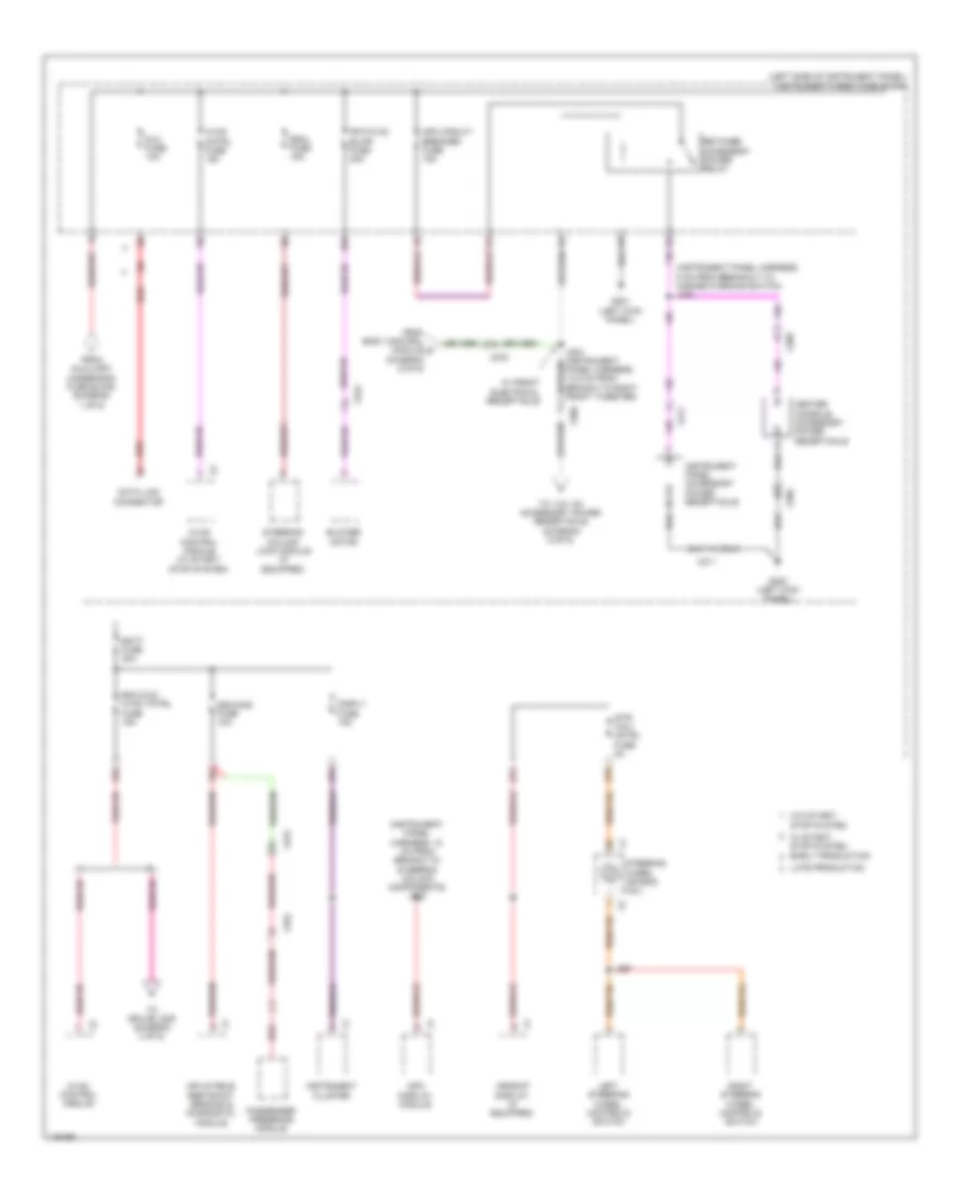
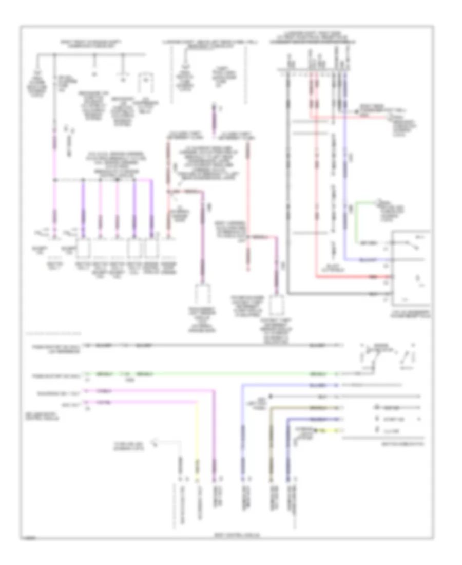
Power Distribution Wiring Diagram (4 of 6) for Cadillac ATS Luxury 2014
List of elements for Power Distribution Wiring Diagram (4 of 6) for Cadillac ATS Luxury 2014:
- (instrument panel harness, 12 cm from branch to steering column components) j202
- (instrument panel harness, 5 cm from breakout to hazard warning switch) j232
- (left side of instrument panel) instrument panel fuse block
- 22a
- 23a
- 24a
- 27a
- 27b
- 33b
- Apo circuit breaker fuse 15a
- Batt fuse 30a
- Blower motor
- Center console accessory power receptacle
- Data link connector
- Disply fuse 15a
- Dlc fuse 10a
- Early production
- Escl fuse 15a
- From auxiliary underhood fuse block (diagram 1 of 6)
- From body control module d (diagram 6 of 6)
- Frt/hvac blwr fuse 40a
- G201 (left kick panel)
- G202 (left kick panel)
- Headup display (if equipped)
- Hvac cntrl fuse 15a
- Hvac control module
- Hvac control module (w/ start/ stop system)
- Inflatable restraint sensing & diagnostic module
- Info display module
- Instrument cluster
- Instrument panel accessory power receptacle
- J297
- Late production
- Left steering wheel controls switch
- Passenger presence module
- Rdo dvd/ hvac tntrl fuse 15a
- Red
- Retained accessory power relay
- Right steering wheel controls switch
- Sdm/aos fuse 10a
- Steering column lock module (if equipped)
- Steering wheel air bag coil
- Str/ whl/ cntrl fuse 2a
- To 110v ac accessory power receptacle (diagram 6 of 6)
- To splice j209 (diagram 3 of 6)
- W/ front electrical receptacle
- W/ start/ stop system
- W/o start/ stop system
- X206
- X211
- X224
- X275
- X322
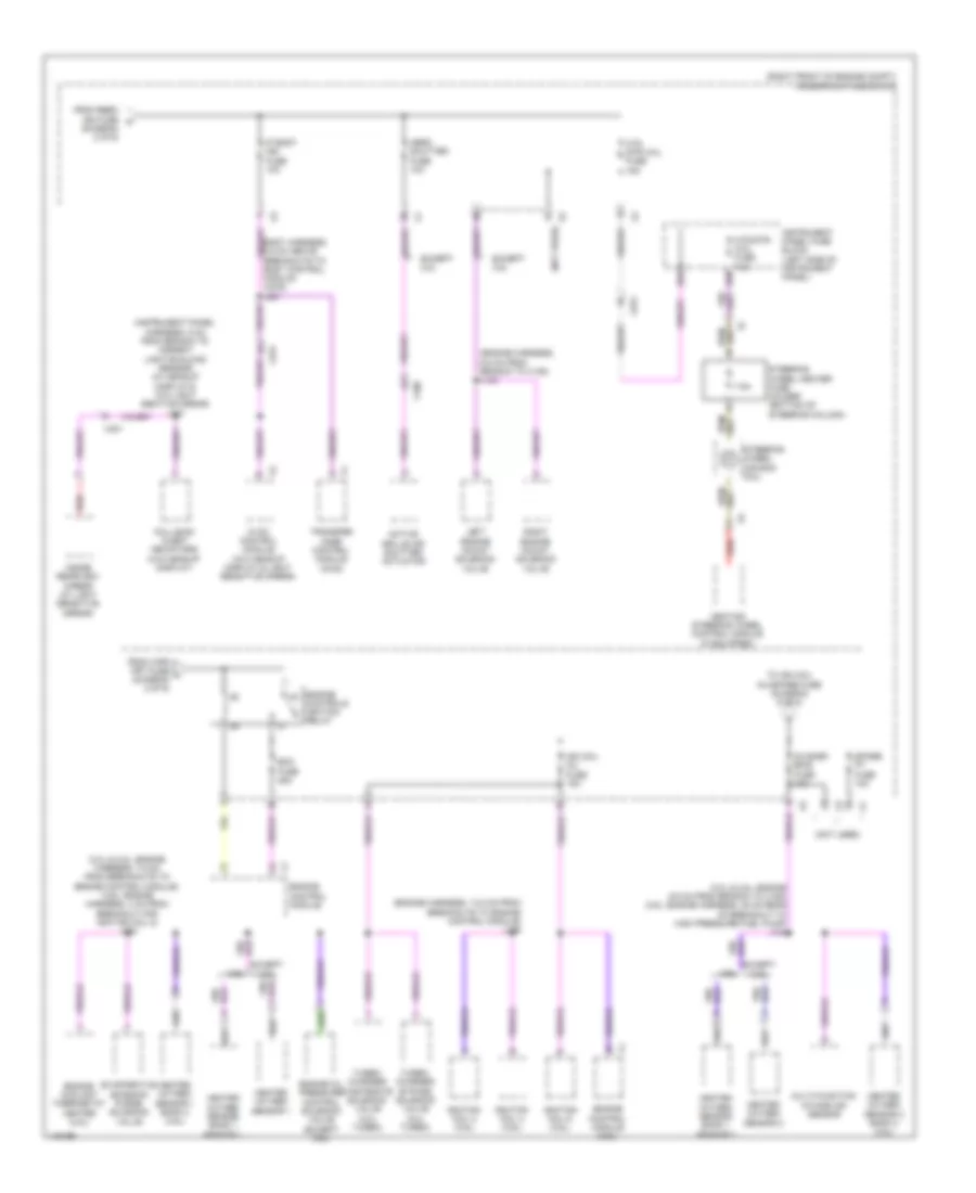
Power Distribution Wiring Diagram (5 of 6) for Cadillac ATS Luxury 2014
List of elements for Power Distribution Wiring Diagram (5 of 6) for Cadillac ATS Luxury 2014:
- (2.0l & 2.5l: engine 9.5 cm from branch to x150) (3.6l: engine harness, 35 cm rear of breakout to high pressure fuel pump) j134
- (2.0l & 2.5l: engine harness, 7.5 cm from breakouts to engine control module) (3.6l: engine harness, 4 cm from breakout for ignition coil 5) j132
- (diagram 2 of 6)
- (engine harness, 13.5 cm from breakouts to engine control module) j136
- (engine harness, 6.5 cm from branch to x150) j140
- (instrument panel harness, 5 cm from branch to ambient light/sunload sensor) (w/ headup display & w/o light sentive mirror) j207
- (not used)
- (right front of engine compt) underhood fuse block
- 25a
- 25b
- 3.6l
- 7.5a
- Active grille air shutter actuator
- Aero shutter fuse 10a
- Body harness, 5.5 cm above breakouts to body control module (awd) j221
- Collision alert indicators (w/o headup display)
- Controls ignition relay
- Ecm fuse 25a
- Engine
- Engine control module
- Engine control module (3.6l)
- Engine coolant thermostat heater (2.5l)
- Engine oil pressure control solenoid valve (except 3.6l)
- Evaporative emission purge solenoid valve
- Except 2.5l
- Except 3.6l
- From rbec ign fuse k
- From wpr frt fuse l (diagram 2 of 6)
- Heated oxygen sensor 1
- Heated oxygen sensor 1 bank 2 (3.6l)
- Heated oxygen sensor 2
- Heated oxygen sensor 2 bank 2 (3.6l)
- Heated oxygen sensor bank 1 sensor 1
- Heated oxygen sensor bank 1 sensor 2
- Heating steering wheel control module (if equipped)
- Htd str whl fuse 15a
- Htd/str/ whl fuse 7.5a
- Hvac control module (w/o headup display & light sensitive mirror)
- Ign coil inj fuse 15a
- Ignition coil 2 (3.6l)
- Ignition coil 4 (3.6l)
- Ignition coil 6 (3.6l)
- Inside rearview mirror (w/ light sensitive mirror)
- Instrument panel fuse block (left side of instrument panel)
- Ip body ign fuse 10a
- Left engine mount solenoid valve
- Multi-function intake air sensor
- O2 snsr emis fuse 10a
- Red
- Right engine mount solenoid valve
- Spare pt fuse 10a
- Steering wheel air bag coil
- Steering wheel heater fuse holder (bottom of steering column)
- To ign coil inj/spare fuse (diagram 6 of 6)
- Transfer case control module (awd)
- Turbo- charger bypass solenoid valve (2.0l turbo)
- Turbo- charger wastegate solenoid valve (2.0l turbo)
- X100
- X275
- X301
Power Distribution Wiring Diagram (6 of 6) for Cadillac ATS Luxury 2014
List of elements for Power Distribution Wiring Diagram (6 of 6) for Cadillac ATS Luxury 2014:
- (2.0l & 2.5l: engine harness, 9.5 cm from breakout to x160) (3.6l: engine harness, 12.5 cm from breakouts to engine control module) j131
- (body harness, 45 cm forward of breakouts to x335 & x337) j347
- (luggage compt, above left rear wheel well) rear body fuse block
- (luggage compt, right side) (w/ front electrical receptacle) accessory dc/ac power inverter module
- (not used)
- (right front of engine compt) underhood fuse block
- (right rear passenger foot well) g304
- (w/ sunroof headliner harness, 20.5 cm forward of breakout to left rear dome/reading lamps) (w/o sunroof headliner harness, 53.5 cm forward of breakout to left rear dome/reading lamps)
- 110v ac accessory power receptacle
- 120v ac phb
- 3.6l
- A/c compressor clutch relay
- Ac inv ctrl
- Acc ind
- Acc led sig ign mode sw
- Acc volt
- Accessory volt
- Body control module
- Content theft deterrent sensor module (w/ interior movement & inclination)
- Drain wire
- Engine control module
- Engine start/stop
- Except 3.6l
- From o2 snsr emis fuse (diagram 5 of 6)
- From rdo/dvd fuse (diagram 3 of 6)
- From rear body fuse block (diagram 2 of 6)
- From splice j203 fuse block (diagram 4 of 6)
- G201 (left kick panel)
- Garage door opener
- Gnd
- Ign 1 volt run/crank
- Ign coil inj/spare fuse 15a
- Ignition coil 1
- Ignition coil 2 (except 3.6l)
- Ignition coil 3
- Ignition coil 4 (except 3.6l)
- Ignition coil 5 (3.6l)
- Ignition mode switch
- Illu ind
- Interior lights system
- J306
- Keyless entry control module
- Mode volt ign mode sw
- Nca
- Passive start sw sig 2
- Passive start sw sig 2 low reference
- Pha 120v ac
- Power sounder content theft deterrent alarm module (if equipped)
- Rain/ambient light sensor module (w/o universal garage door)
- Rap rly2 coil ctrl
- Red
- Run/crank ign 1 volt
- Secondary air injection pump relay (california emission system)
- Secondary air injection solenoid valve relay (california emission system)
- Start ind
- Start led sig ign mode sw
- Theft mdl/ugdo/ rain snsr fuse 5a
- To splice j203 (diagram 4 of 6)
- Volt batt pos
- W/ horn theft deterrent alarm
- W/ universal garage door
- W/o horn theft deterrent alarm
- X206
- X225
- X275
- X306
- X335
- X337