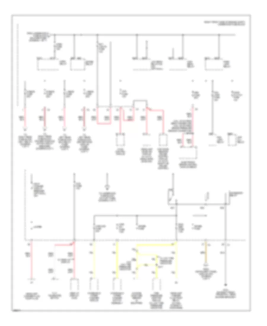
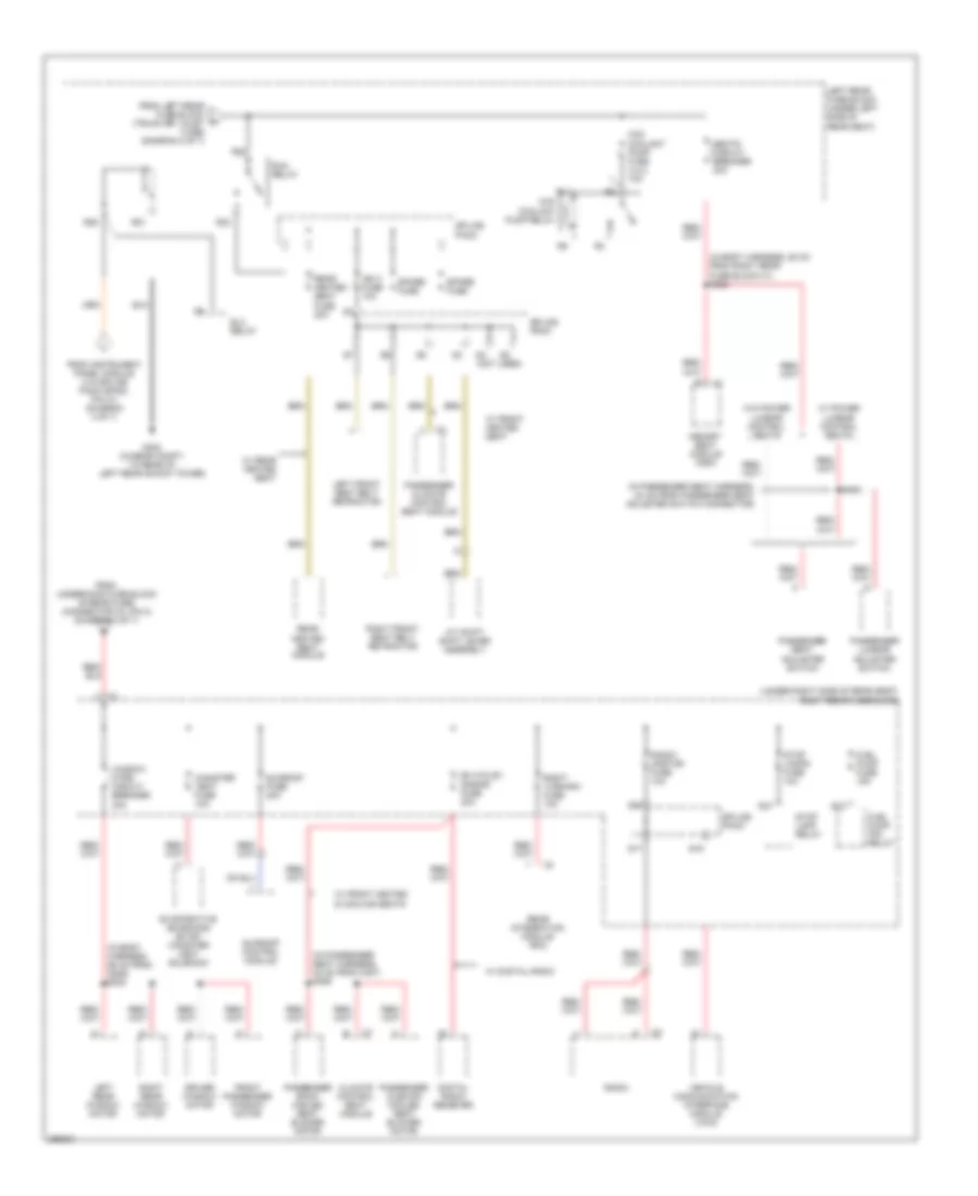
POWER DISTRIBUTION
Power Distribution Wiring Diagram (1 of 7) for Cadillac STS V 2007

List of elements for Power Distribution Wiring Diagram (1 of 7) for Cadillac STS V 2007:
- (3.6l & 4.6l)
- (3.6l)
- (3.6l: in engine harness, 27 cm from evap canister purge solenoid valve connector) (4.6l: in engine harness, 15 cm from fuel injector 5 connector) s101
- (4.4l)
- (4.6l)
- (engine harness, 36 cm from tcm connector)
- (in engine poa harness, 18 cm from ignition coil 1 connector) s127
- (in ignition coil harness, 30 cm from ignition coil module 1 connector) s142
- (not used)
- (right front side of engine compt) underhood fuse block
- 3.6l
- 4.4l
- 4.6l
- 4.6l/ 4.4l
- Automatic headlamp dimming relay
- Battery
- Blower fuse 40a
- Blower relay
- C1 h
- Camshaft position (cmp) actuator solenoid exhaust bank 1
- Camshaft position (cmp) actuator solenoid exhaust bank 2
- Camshaft position (cmp) actuator solenoid intake bank 1
- Camshaft position (cmp) actuator solenoid intake bank 2
- Data link connector (dlc)
- Ecm/tcm fuse 10a
- Engine control
- Engine control module (ecm)
- Evaporative emissions (evap) canister purge solenoid valve
- Fuel injector
- Fusible link
- Generator
- Heated oxygen sensor (ho2s) bank 1 sensor 1
- Heated oxygen sensor (ho2s) bank 2 sensor 1
- Hfv6 ecm fuse 15a
- Hi fan fuse 30a
- High speed fan relay
- Ignition coil 1
- Ignition coil 3
- Ignition coil 5
- Ignition coil/ module
- Instrument panel cluster (ipc)
- Instrument panel module (ipm)
- Intake manifold runner control (imrc) solenoid
- Ipm/ aldl fuse 10a
- Low fan fuse 30a
- Low speed fan relay
- Module (ecm)
- Odd coils fuse 15a
- Pnk/ (in engine harness, 14 cm from fuel injector 7 connector) s102
- Powertrain relay
- Pre o2/ cam fuse 15a
- R14
- R19
- R20
- R39
- R40
- R47
- R48
- R49
- R50
- R51
- R52
- Red
- Remote control door lock receiver (rcdlr)
- S/p fan relay
- S109
- S136
- Smt-bm fuse (optional) 10a
- Starter
- To underhood fuse block (horn fuse) (diagram 2 of 7)
- To underhood fuse block (post o2 fuse) (diagram 3 of 7)
- Transmission control module (tcm)
- V8 ecm fuse 10a
- Vacuum bypass
- Valve
- Volt check fuse 10a
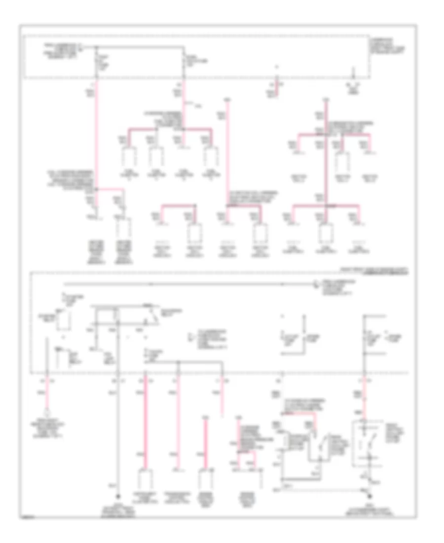
Power Distribution Wiring Diagram (2 of 7) for Cadillac STS V 2007
List of elements for Power Distribution Wiring Diagram (2 of 7) for Cadillac STS V 2007:
- (3.6l: 30 cm from ebcm connector) (4.6l: 25 cm from brake pressure sensor connector) s118
- (right front side of engine compt) underhood fuse block
- (w/ auto headlamps leveling)
- Abs fuse 50a
- Accessory relay
- Ccp fuse 10a
- Cmp clu relay
- Comp clutch fuse 10a
- Distance sensing cruise control module (w/ auto adaptive cruise control)
- Electronic brake control module (ebcm)
- Ext lights fuse 10a
- Fog lamp fuse 15a
- Fog lamp relay
- From instrument panel module (ipm) (diagram 4 of 7)
- From underhood fuse block a (blower fuse) (diagram 1 of 7)
- G104 (on right front frame rail, near bumper bracket)
- Hdlp washer circuit breaker (optional) 30a
- Head up display (hud)
- Headlamp leveling module
- Headlamp washer fluid pump fluid
- Headlamp washer fluid pump relay (w/ high intensity discharge)
- High beam relay
- Horn fuse 15a
- Horn relay
- Hud fuse 10a
- Hvac control module
- Jumper
- L rear fuse 60a
- Low beam relay/hid mini (optional)
- Outside moisture sensor (if equipped)
- Park lamp relay
- R rear fuse 60a
- R10
- R11
- R23
- R24
- R27
- R28
- R31
- R32
- R35
- R36
- R37
- R38
- R56
- Rain ssr fuse 7.5a
- S411
- Spare fuse
- Spare relay
- Tilt/ telescope switch
- Tire pressure monitor module (w/ low tire pressure indicator)
- To left rear fuse block (driver door module fuse) (diagram 5 of 7)
- To left rear fuse block (elc relay fuse) (diagram 5 of 7)
- To right rear fuse block (ign 1 relay) (diagram 7 of 7)
- To right rear fuse block (power windows motor circuit breaker) (diagram 6 of 7)
- To underhood fuse block (outlet fuse) (diagram 3 of 7)
- W/ head up display
- W/ low tire pressure indicator
- W/o low tire pressure indicator
- Windshield wiper/ washer module
- Windshield wiper/ washer switch assembly
- Wpr mod fuse 30a
- Wpr sw fuse 7.5a
Power Distribution Wiring Diagram (3 of 7) for Cadillac STS V 2007
List of elements for Power Distribution Wiring Diagram (3 of 7) for Cadillac STS V 2007:
- (3.6l: in engine harness, 52 cm from ho2s bank 1 sensor 2 connector) (4.6l: in engine harness, 34 cm from c102) s104
- (in console harness, 31 cm from hazard switch connector) s312
- (in engine harness, 16 cm from fuel injector 8 connector) s103
- (in engine harness, 39 cm from brake pressure sensor connector) s105
- (in engine poa harness, 25 cm from ignition coil 2 connector) s119
- (in ignition coil harness, 36 cm from ignition coil module 2 connector) s131
- (in passenger compt, behind right kick panel)
- (not used)
- (right front side of engine compt) underhood fuse block
- 3.6l
- 4.6l
- Cmp clu relay
- Console auxiliary power outlet
- Engine control module (ecm)
- Even coils fuse 15a
- Fog lamp relay
- From right rear fuse block (run/crank fuse, 10a) (diagram 7 of 7)
- From underhood fuse block (hud fuse) (diagram 2 of 7)
- From underhood fuse block c (pre o2/cam fuse) (diagram 1 of 7)
- Front ashtray auxiliary power outlet
- Fuel injector
- Fuel injector 2
- Fuel injector 4
- Fuel injector 6
- G104 (on right front frame rail, near bumper bracket)
- G201
- Heated oxygen sensor (ho2s) bank 1 sensor 2
- Heated oxygen sensor (ho2s) bank 2 sensor 2
- I/p outlet fuse 15a
- Ignition coil 2
- Ignition coil 4
- Ignition coil 6
- Ignition coil/ module 2
- Ignition coil/ module 4
- Ignition coil/ module 6
- Ignition coil/ module 8
- Instrument panel cluster (ipc)
- Nca
- Outlet fuse 20a
- Pnk
- Post fuse 10a
- R43
- R44
- R45
- R46
- R55
- R64
- Rear ashtray auxiliary power outlet
- Red
- Run/crank relay
- S137
- S212
- S311
- Spare fuse
- Starter fuse 30a
- Starter relay
- Tcm/ipc fuse 15a
- To underhood fuse block (wash noz/aqs fuse) (diagram 4 of 7)
- Transmission control module (tcm)
- Underhood fuse block (right front side of engine compt)
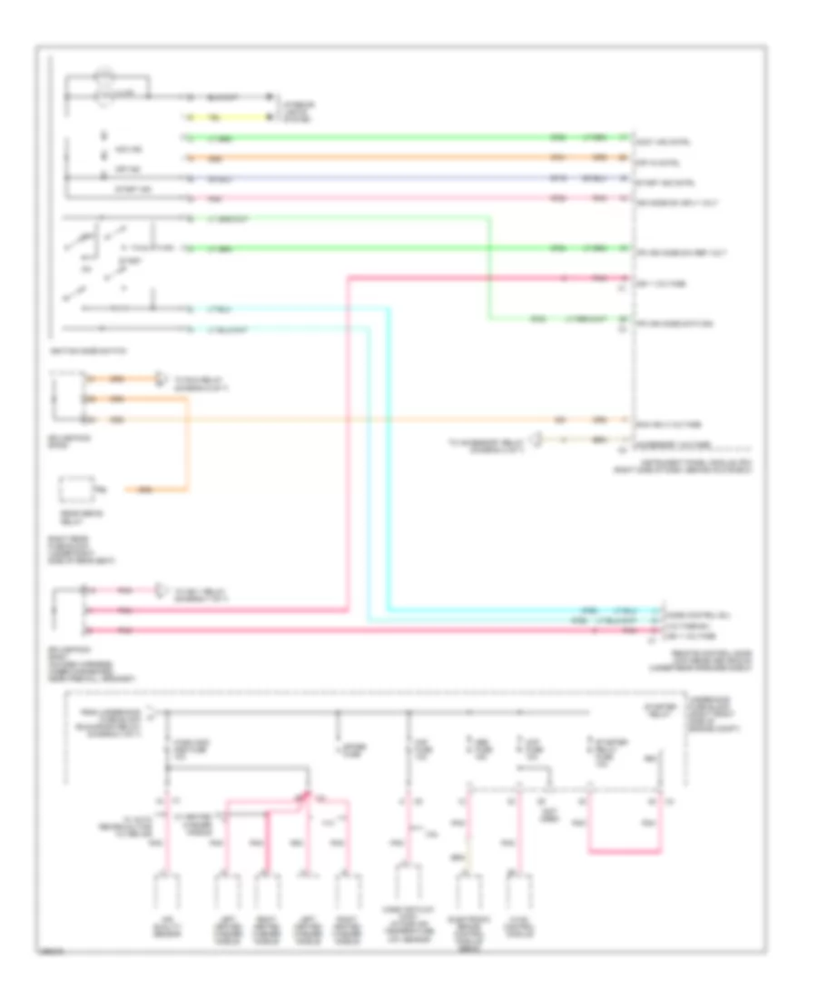
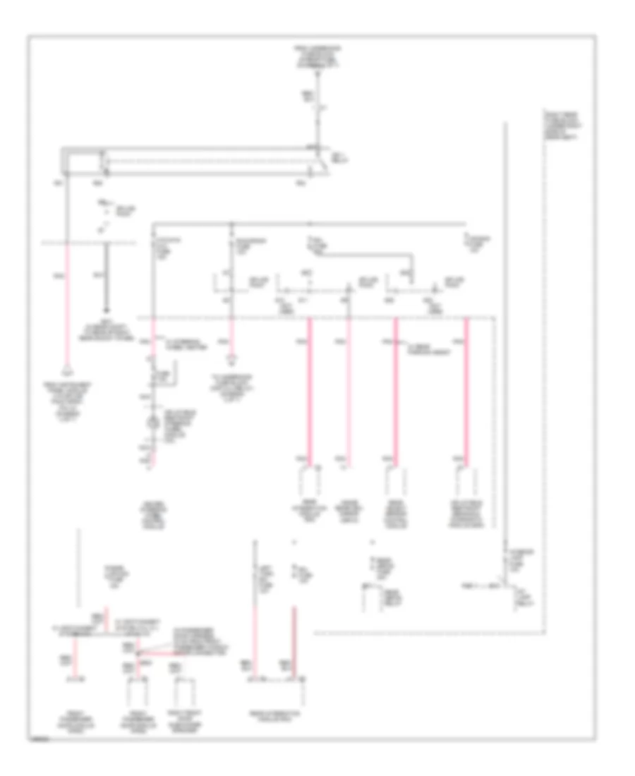
Power Distribution Wiring Diagram (4 of 7) for Cadillac STS V 2007
List of elements for Power Distribution Wiring Diagram (4 of 7) for Cadillac STS V 2007:
- (not used)
- 3.6l
- 4.4l
- Abs fuse 15a
- Acc ind
- Accessory voltage
- Accy ind cntrl
- Air quality sensor
- Ccp fuse 10a
- Electronic brake control module (ebcm)
- From underhood fuse block (run/crank relay) (diagram 3 of 7)
- Hvac control module
- Ign 1 voltage
- Ign mode sw sply volt
- Ignition mode switch
- Illum
- Instrument panel module (ipm) (right side of dash, behind glove box)
- Interior lights system
- Ipm ign mode data sig
- Ipm ign mode sw ref volt
- Left heated washer nozzle
- Maf fuse 10a
- Mass air flow (maf)/ intake air temperature (iat) sensor
- Mode control b/u
- Off
- Off in cntrl
- Off ind
- Pnk
- R63
- Rear defog relay
- Remote control door lock receiver (rcdlr) (under rear speaker shelf)
- Right heated washer nozzle
- Right rear fuse block (under right side of rear seat)
- Run ign 3 voltage
- Spare fuse
- Splice pack sp201 (on dash harness, under dashboard, near firewall grommet)
- Splice pack sp300
- Start
- Start ind
- Start ind cntrl
- Starter relay
- Starter relay fuse 10a
- To accessory relay (diagram 2 of 7)
- To ign 1 relay (diagram 7 of 7)
- To run relay (diagram 6 of 7)
- Underhood fuse block (right front side of engine compt)
- Voltage b/u
- W/ auto recircualting filter air
- W/ heated washer nozzle
- Wash noz/ aqs fuse 10a
Power Distribution Wiring Diagram (5 of 7) for Cadillac STS V 2007
List of elements for Power Distribution Wiring Diagram (5 of 7) for Cadillac STS V 2007:
- (in driver door harness, 54 cm from c500) s502
- (in passenger seat harness, 17 cm from passenger seat adjuster switch connector) s354
- (under left side of rear seat) left rear fuse block
- Air bag fuse 10a
- Amp fuse 30a
- Audio amplifier (w/ infotainment system 010, 012, 014 & 015)
- Automatic level control (alc) compressor
- Automatic transmission shift lever assembly
- Dpm fuse 10a
- Driver back cooled seat blower motor
- Driver cushion cooled seat blower motor
- Driver door module (ddm)
- Driver door module fuse 15a
- Driver lumbar adjuster switch
- Driver seat adjuster switch
- Elc relay
- Elc relay fuse 30a
- Elc sol fuse 10a
- Electronic suspension control (esc) module
- From underhood fuse block (l rear fuse) (connector c2, pin 1) (diagram 2 of 7)
- From underhood fuse block (l rear fuse) (connector c2, pin 2) (diagram 2 of 7)
- Inflatable restraint sensing & diagnostic module (sdm)
- Joint connector
- Left front door subwoofer speaker
- Left position lamp relay
- Left rear door module (lrdm)
- Memory seat module (msm)
- Mr-rtd mod fuse 25a
- Nca
- Position lamp fuse 10a
- R13
- R18
- R28
- R29
- R31
- R32
- R36
- R37
- Rear dr mod fuse 15a
- Rear subwoofer speaker
- Rev lamp relay
- Reverse lamp fuse 10a
- Right position lamp relay
- Right rear door module (rrdm)
- Rr shlf speaker fuse (sub woofer) 15a
- S12
- S13
- S14
- S20
- S21
- S22 (not used)
- S23
- Spare fuse
- Splice pack
- Stndby lamp relay
- Theft/ shifter fuse 10a
- To left rear fuse block (run relay) (diagram 6 of 7)
- Trk dr rel relay
- Trunk dr/ valet fuse 10a
- Tv antenna module
- Tv/vics fuse 10a
- W/ front climate control seat
- W/ infotainment system 010
- W/ infotainment system 011,012, 014 & 015
- W/ infotainment system 012, 014 & 015
- W/ infotainment system 014 & 015
- W/ magnetic ride control
- W/ memory
- W/ power lumbar control seat
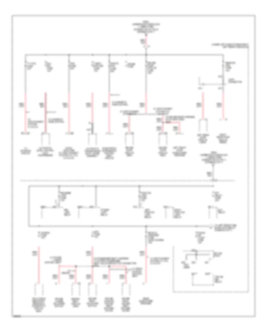
Power Distribution Wiring Diagram (6 of 7) for Cadillac STS V 2007
List of elements for Power Distribution Wiring Diagram (6 of 7) for Cadillac STS V 2007:
- (in body harness, 58 cm from right rear fuse block c1) s302
- (in body harness, 86 cm from g306) s303
- (in passenger seat harness, 24 cm from passenger seat adjuster switch connector)
- (in passenger seat harness, 32 cm from c307) s355
- (not used)
- (under right side of rear seat) right rear fuse block
- A/t shift shift lever assembly
- Cac coolant pump fuse (4.4l) 10a
- Cac coolant pump relay
- Canister vent fuse 10a
- Climate control seat module
- Digital radio receiver
- Driver window motor
- Elc relay
- Evaporative emissions (evap) canister vent solenoid
- From instrument panel module (via splice pack sp300, pin 31) (diagram 4 of 7)
- From left rear fuse block (trunk dr/ valet fuse) (diagram 5 of 7)
- From underhood fuse block (r rear fuse) (connector c3, pin 2) (diagram 2 of 7)
- Front passenger window motor
- Fuel pump (fp) relay
- Fuel pump fuse 15a
- G402 (in rear compt, to rear of left rear shock tower)
- Ign 3 fuse 10a
- Left front seat belt retractor
- Left rear fuse block (under left side of rear seat)
- Left rear window motor
- Memory seat module (msm)
- Passenger back cooled seat blower motor
- Passenger climate control seat module
- Passenger cushion cooled seat blower motor
- Passenger lumbar adjuster switch
- Passenger seat adjuster switch
- R12
- R21
- R22
- R23
- R25
- R37
- Radio
- Radio/ onstar fuse 10a
- Rear heated seat fuse 20a
- Rear heated seat module
- Rear integration module (rim)
- Rf htd st/ s-band fuse 20a
- Right front seat belt retractor
- Right rear window motor
- Right turn-rim fuse 10a
- Run relay
- S15
- S16
- S17
- S353
- Seats circuit breaker 30a
- Spare fuse
- Splice pack
- Stop lamp relay
- Stop lamps fuse 10a
- Sunroof control module
- Sunroof fuse 20a
- Vehicle communication interface module (vcim)
- W/ digital radio
- W/ front heated & cooling seats
- W/ front heated seat
- W/ power lumbar control seats
- W/ rear heated seat
- W/o power lumbar control seats
- Window mtrs circuit breaker 30a
Power Distribution Wiring Diagram (7 of 7) for Cadillac STS V 2007
List of elements for Power Distribution Wiring Diagram (7 of 7) for Cadillac STS V 2007:
- (in passenger door harness, 34 cm from front passenger window motor connector)
- Air bag fuse 10a
- D pnk
- From instrument panel module (via splice pack sp201, pin 10) (diagram 4 of 7)
- From underhood fuse block (r rear fuse) (diagram 2 of 7)
- Front passenger door module (fpdm)
- Fuse 7.5a
- G401 (in rear compt, to rear of right rear shock tower)
- Heated steering wheel control module
- Htd stg/ clm fuse 15a
- Ign 1 relay
- Inflatable restraint sensing & diagnostic module (sdm)
- Inflatable restraint steering wheel module coil
- Inside rearview mirror (isrvm)
- Int lamp relay
- Interior lamp fuse 10a
- Left turn rim fuse 10a
- Nca
- Pnk
- Psgr dr mod fuse 15a
- R16
- R17
- R21
- R22
- R23
- R25
- Rear defog fuse 40a
- Rear defog relay
- Rear integration module (rim)
- Rear object sensor control module
- Right front door subwoofer speaker
- Right rear fuse block (under right side of rear seat)
- Rim fuse 10a
- Run/crank fuse 10a
- S10 (not used)
- S11
- S22
- S23 (not used)
- S25
- Splice pack
- To underhood fuse block (cmp clu relay) (diagram 3 of 7)
- W/ infotainment system 010
- W/ infotainment system 012, 011, 014 & 015
- W/ rear parking assist
- W/ steering wheel heater