POWER DISTRIBUTION
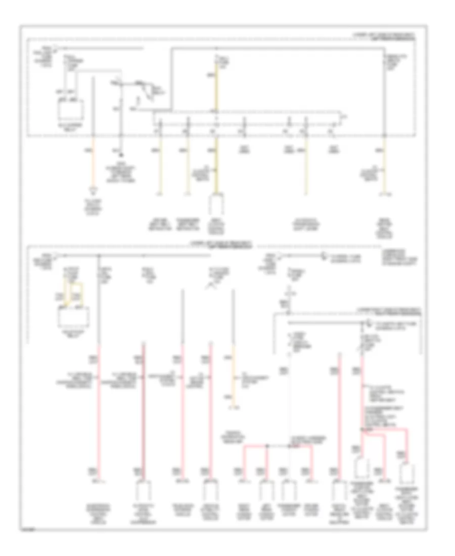
Power Distribution Wiring Diagram (1 of 6) for Cadillac STS V 2009

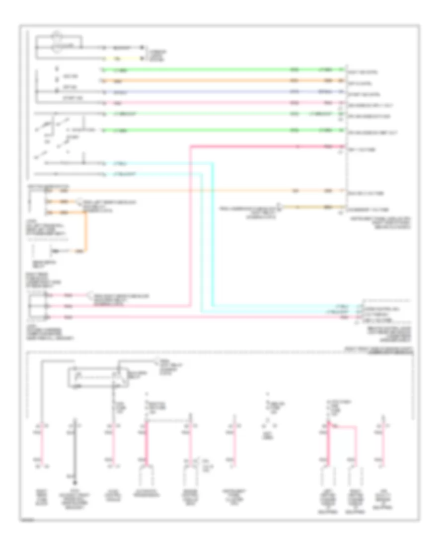
List of elements for Power Distribution Wiring Diagram (1 of 6) for Cadillac STS V 2009:
- (in passenger seat harness, 24 cm from passenger seat adjuster switch connector) j353
- (right front side of engine compt) underhood fuse block
- (under left side of rear seat) left rear fuse block
- 200a
- Abs fuse 25a
- Abs mtr fuse 50a
- Air bag/ batt fuse 10a
- Amp fuse 30a
- Audio amplifier
- Battery
- Bck/up lamp fuse 10a
- Bck/up lamp relay
- Ddm fuse 15a
- Driver back ventilated seat blower motor
- Driver cushion ventilated seat blower motor
- Driver door module (ddm)
- Driver seat adjuster switch
- Driver seat lumbar switch
- Electronic brake control module (ebcm)
- Generator
- Inflatable restraint sensing & diagnostic module (sdm)
- Inline fuse generator
- J/c
- J302 (in body harness, 58 cm from right rear fuse block c1)
- Left front speaker
- Left rear door control module
- Left rear fuse block (under left side of rear seat)
- Lpdb 1 fuse 50a
- Lpdb 2 fuse 50a
- Lt pos relay
- Memory seat module (msm)
- Memory seat module (msm) (if equipped)
- Msm fuse 10a
- Passenger seat adjuster switch
- Passenger seat lumbar switch
- Pos lamp fuse 10a
- Pwr seats circuit breaker 30a
- R13
- R18
- R26
- R29
- R31
- R32
- R36
- R37
- Rear dr mdl fuse 15a
- Rear shlf spkr fuse 15a
- Red
- Red/ (in passenger seat harness, 17 cm from passenger seat adjuster switch connector) j354
- Right rear door control module
- Rt pos relay
- S12
- S13
- S14
- S20
- S21
- S22
- S23
- Speaker
- Starter motor
- Stdby lamp relay
- Subwoofer
- To elc cmprsr fuse (diagram 2 of 6)
- To inclr pump fuse (diagram 2 of 6)
- To rpdb 2 fuse (diagram 2 of 6)
- Trunk relse relay
- Trunk relse sw fuse 7.5a
- Valet switch
- W/ climate control seats
- W/ infotainment system 010
- W/ infotainment system 012/014/015
- W/ power lumbar seat
- W/o power lumbar seat
- X1 b
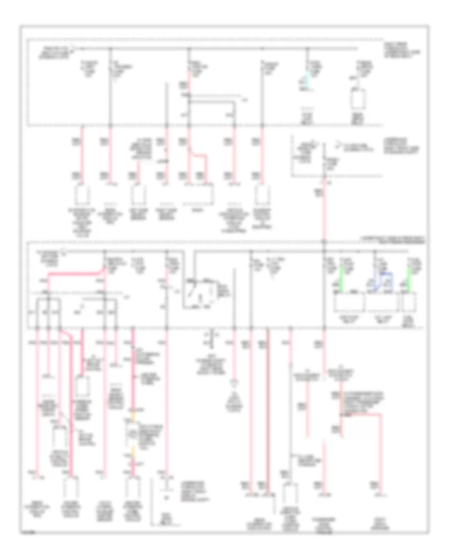
Power Distribution Wiring Diagram (2 of 6) for Cadillac STS V 2009
List of elements for Power Distribution Wiring Diagram (2 of 6) for Cadillac STS V 2009:
- (in body harness, 86 cm from g306) j303
- (in passenger seat harness, 32 cm from x307) (w/ climate control seats) j355
- (not used)
- (under left side of rear seat) left rear fuse block
- (under right side of rear seat) right rear fuse block
- Automatic level control (alc) compressor
- Automatic transmission shift lever
- B x1
- C x2
- Digital radio receiver (if equipped)
- Driver seat belt retractor
- Driver window motor
- Elc cmprsr fuse 30a
- Elc cmprsr relay
- Elc exh fuse 10a
- Electronic suspension control (esc) module
- From a lpdb 1 fuse (diagram 1 of 6)
- From b pos lamp fuse (diagram 1 of 6)
- From c ddm fuse (diagram 1 of 6)
- G402 (in rear compt, to rear of left rear shock tower)
- Ign 3 fuse 10a
- Inclr pump fuse 10a
- Inclr pump relay
- J/c
- Left rear window motor
- Mrtd mdl fuse 25a
- Passenger back ventilated seat blower motor (w/ climate control seats)
- Passenger cushion ventilated seat blower motor (w/ climate control seats)
- Passenger seat belt retractor
- Passenger window motor
- R21
- R22
- R23
- R25
- Rear heated seat control module
- Rear htd/ seats fuse 20a
- Rf htd/ seat/xm fuse 20a
- Right rear window motor
- Rpdb 2 fuse 50a
- Run relay
- Seat climate control module
- Television antenna module
- To cnstr vent fuse (diagram 3 of 6)
- To jx300 (pin 31) (diagram 6 of 6)
- To rpdb 1 fuse (diagram 3 of 6)
- Traffic information receiver
- Tv/vics/ afs/scm fuse 10a
- Underhood fuse block (right front side of engine compt)
- Vehicle stability control module
- W/ active brake control
- W/ climate control seats
- W/ climate control seats & front heater seat
- W/ infotainment system
- W/ infotainment system 014/015
- W/ variable real time damping magneto rheological
- Wndw mtrs circuit breaker 30a
Power Distribution Wiring Diagram (3 of 6) for Cadillac STS V 2009
List of elements for Power Distribution Wiring Diagram (3 of 6) for Cadillac STS V 2009:
- (under right side of rear seat) right rear fuse block
- A x3
- Cnstr vent fuse 10a
- D x276
- Diff pump fuse 15a
- Diff pump relay
- Evaporative emission (evap) canister vent solenoid valve
- From d rpdb 2 fuse (diagram 2 of 6)
- From rf htd/ e seat/xm fuse (diagram 2 of 6)
- Frt pdm fuse 15a
- Fuel pump fuse 20a
- Fuel pump relay
- G401 (in rear compt, to rear of right rear shock tower)
- Harness)
- Heated steering wheel control module
- Heater steering wheel
- Htd str fuse 7.5a
- Inflatable restraint steering wheel module coil
- Inside rearview mirror (isrvm)
- Int lamp fuse 10a
- Int lamp relay
- J/c
- J221 (in steering column pnk
- J407
- Left side object sensor
- Lt trn/ ldw fuse 10a
- Passenger door control module
- Pnk
- Power steering control module
- R12
- R16
- R17
- R21
- R22
- R23
- R25
- R26
- R27
- R37
- Radio
- Rdo/ onstar fuse 10a
- Rear defog relay
- Rear integration module (rim)
- Rear object sensor control module
- Rear/ defog fuse 40a
- Red/ (in passenger door harness, 34 cm from front passenger window motor connector) j602
- Right front speaker
- Right rear fuse block (under right side of rear seat)
- Right side object sensor
- Rim fuse 10a
- Rim/rpa/ isrvm/clm fuse 10a
- Rpdb 1 fuse 50a
- Rt trn/sbza fuse 10a
- Run/ crnk fuse 10a
- Run/ crnk relay
- S/roof fuse 20a
- S10
- S11
- S15
- S16
- S17
- S22
- S23
- S24
- S25
- Steering wheel speed/ position sensor
- Stop lamp relay
- Stop lamps fuse 10a
- Sunroof control module (if equipped)
- Tan
- To afs fuse (diagram 4 of 6)
- To air bag/ ign fuse (diagram 4 of 6)
- To jx201 (pin 10) (diagram 6 of 6)
- Underhood fuse block (right front side of engine compt)
- Vehicle communication interface module (vcim) (if equipped)
- Vehicle direction alert alarm warning module
- Vehicle stability control module
- W/ active brake control
- W/ infotainment system 010
- W/ infotainment system 012/ 014/015
- W/ lane departure warning
- W/ side obstacle detection sensor indicator
- X277 d
- Yaw & lateral acceler ometer sensor
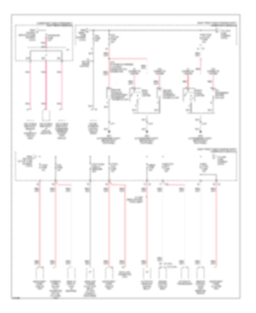
Power Distribution Wiring Diagram (4 of 6) for Cadillac STS V 2009
List of elements for Power Distribution Wiring Diagram (4 of 6) for Cadillac STS V 2009:
- (3.6l)
- (4.4l/4.6l)
- (right front side of engine compt) underhood fuse block
- (under right side of rear seat) right rear fuse block
- Afs fuse 30a
- Air bag/ign fuse 10a
- Automatic headlamp dimming relay
- Automatic transmission
- Aux outlet fuse 20a
- Center console accessory power outlet
- Center console compartment accessory power outlet
- Data link connector (dlc)
- Ecm/tcm batt fuse 10a
- Ekm/ ip mdl fuse 10a
- Engine control module (ecm)
- From f rpdb 1 fuse (diagram 3 of 6)
- From g rim/rpa/ isrvm/clm fuse (diagram 3 of 6)
- From h frt pwr outlet fuse (diagram 4 of 6)
- Front cigar lighter
- Frt pwr outlet fuse 15a
- G201 (in passenger compt, behind right kick panel)
- Hdlp wash circuit breaker 30a
- Head up display (hud) (if equipped)
- Headlamp washer fluid pump relay (w/ high intensity discharge)
- Hud fuse 10a
- I/beam fuse 15a
- I/p accessory power outlet
- I/p mdl/ aldl fuse 10a
- Inflatable restraint i/p module indicator
- Inflatable restraint passenger presence system (pps) module
- Inflatable restraint sensing & diagnostic module (sdm)
- Instrument panel cluster (ipc)
- Instrument panel module (ipm)
- J/c
- J212
- J311
- Pnk
- Power steering control module (pscm)
- Rear cigar lighter
- Red
- Remote control door lock receiver (rcdlr)
- S18
- S19
- S20
- S21
- Steering wheel/ column tilt/ telescope switch (w/ alarm taxi)
- To v/chk fuse (diagram 4 of 6)
- To wpr fuse (diagram 5 of 6)
- V/chk fuse 10a
- W/ active brake control
- W/ cigarette lighter
- W/ high beam control intelligent
- W/o cigarette lighter
- X1 h
Power Distribution Wiring Diagram (5 of 6) for Cadillac STS V 2009
List of elements for Power Distribution Wiring Diagram (5 of 6) for Cadillac STS V 2009:
- (in body harness, 55.5 cm from x305 inline connector) (w/ wiper system) j411
- (right front side of engine compt) underhood fuse block
- A/c cltch fuse 10a
- A/c cmprsr cltch relay
- Accy relay
- Blwr fuse 40a
- Ccp/ rly coils fuse 10a
- Distance sensing cruise control (dscc) module
- Fan 1 fuse 30a
- Fan 2 fuse 30a
- Fog lamp relay
- From ekm/ i i/p mdl fuse (diagram 4 of 6)
- From j blwr fuse (diagram 5 of 6)
- Frt blwr relay
- Fuel cool fuse 10a
- Fuel cool relay
- G104 (on right front frame rail, near bumper bracket)
- Headlamp leveling module (if equipped)
- Headlamp washer fluid pump relay (if equipped)
- Hi beam relay
- Hi fan spd relay
- Hid
- Horn fuse 15a
- Horn relay
- Hvac control module
- Lo beam w/o hid/ hid relay
- Lo fan spd relay
- Prk lamp relay
- Pwr/trn relay
- Rain snsr/ tpm fuse 7.5a
- Strtr fuse 30a
- Strtr relay
- Tire pressure module (if equipped)
- To instrument panel module (ipm) (pin 1 connector x2) (diagram 6 of 6)
- To pwr/trn relay (diagram 5 of 6)
- To run crnk relay (diagram 6 of 6)
- Traffic information receiver
- W/ adaptive automatic cruise control
- W/ cover wheel
- W/ infotainment system 015
- W/ tire pressure
- W/ wiper system
- W/o cover wheel
- W/o tire pressure
- Windshield outside moisture sensor (if equipped)
- Windshield wiper inhibit relay
- Windshield wiper/ washer switch
- Wpr fuse 30a
- Wpr hi relay
- Wpr spd relay
- Wpr sw/vics fuse 7.5a
- X320
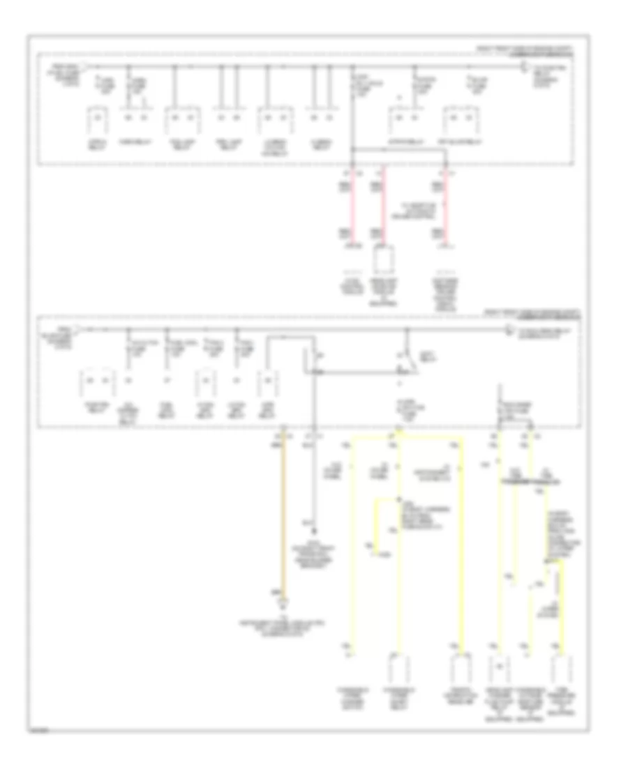
Power Distribution Wiring Diagram (6 of 6) for Cadillac STS V 2009
List of elements for Power Distribution Wiring Diagram (6 of 6) for Cadillac STS V 2009:
- (not used)
- (right front side of engine compt) underhood fuse block
- 3.6l
- 4.4l & 4.6l
- Abs ign fuse 15a
- Acc ind
- Accessory voltage
- Accy ind cntrl
- Air quality sensor (if equipped)
- Automatic transmission
- Ccp fuse 10a
- Ecm/tcm ign fuse 15a
- Engine control module (ecm)
- From accy relay (diagram 5 of 6)
- From left rear fuse block (run relay) (diagram 2 of 6)
- From right rear fuse block (run/crnk relay) (diagram 3 of 6)
- From underhood fuse block n (accy relay) (diagram 5 of 6)
- G104 (on right front frame rail, near bumper bracket)
- Htd wash/ aqs fuse 10a
- Hvac control module
- Ign 1 voltage
- Ign mode sw sply volt
- Ignition mode switch
- Illum
- Instrument panel cluster (ipc)
- Instrument panel module (ipm) (right side of dash, behind glove box)
- Interior lights system
- Ipm ign mode data sig
- Ipm ign mode sw ref volt
- Jx201 (on dash harness, under dashboard, near firewall grommet)
- Jx300 (on left frame rail, near left side of passenger seat)
- Left heated washer nozzle (if equipped)
- Mode control b/u
- Off
- Off in cntrl
- Off ind
- Pnk
- Rear defog relay
- Remote control door lock receiver (rcdlr) (under rear speaker shelf)
- Right heated washer nozzle (if equipped)
- Right rear fuse block
- Right rear fuse block (under right side of rear seat)
- Run crnk relay
- Run ign 3 voltage
- Start
- Start ind
- Start ind cntrl
- Voltage b/u