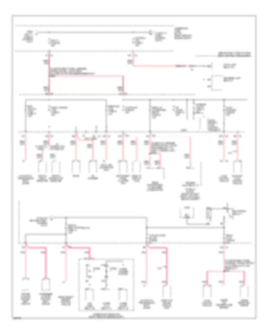
POWER DISTRIBUTION
Power Distribution Wiring Diagram (1 of 4) for Cadillac XLR V 2007

List of elements for Power Distribution Wiring Diagram (1 of 4) for Cadillac XLR V 2007:
- (front of right front footwell, behind carpet) i/p fuse block
- (in instrument panel harness, approximately 10.5 cm from bcm breakout)
- (in instrument panel harness, approximately 14.5 cm from bcm breakout)
- (in passenger's seat harness, approximately 20.5 cm from lumbar switch) s380
- (not used) c400
- (right rear of engine compt) underhood fuse block
- A c1
- A/c comp fuse 15 10a
- A/c comp relay 35
- A18
- A19
- A2 c2
- A2 c4
- Abs fuse 27 60a
- Amp fuse 31 30a
- Audio amplifier
- Automatic transmission
- B1 c4
- Batt 1 fuse 33 60a
- Batt 2 fuse 29 40a
- Battery
- Blower motor control processor
- C14
- Coolfan fuse 25 60a
- Crank relay 43
- D c1
- D11
- D11 c3
- Dr cntrls circuit breaker 34 30a
- Driver climate control seat module
- Driver door module (ddm)
- Driver lower lumbar switch
- Driver memory seat module
- Driver seat pump
- Driver upper lumbar switch
- Ecm/tcm fuse 11 15a
- Electronic brake control module (ebcm)
- Electronic suspension control (esc) module
- Engine control module (ecm)
- Evaporative emission (evap) canister vent solenoid
- F12 c3
- Fan control module
- Fog lp fuse 22 15a
- Fog lp relay 38
- Folding top module
- Front passenger door module (fpdm)
- Front passenger seat adjuster switch
- Front passenger seat pump
- Fuel door relay 52
- Generator
- H c1
- H13
- H14
- Hdlp wash fuse 18 20a
- Hdlp wash relay 46
- High beam relay 39
- Horn fuse 2 15a
- Horn relay 34
- Hvac fuse 28 40a
- I/p relay block (front of right front footwell, behind carpet)
- Ign 1 relay 44
- K10
- K14
- Left heated seat fuse 42 15a
- Left/right power lumbar fuse 40 15a
- Low beam relay 47
- Mrrtd fuse 13 25a
- Nca
- Park lamp relay 37
- Passenger climate control seat module
- Passenger lower lumbar switch
- Passenger upper lumbar switch
- Pk lamps fuse 8 10a
- Power seats circuit breaker 33 30a
- Rear defog relay 40
- Red
- Red/ (in engine harness, approximately 23.5 cm from ebcm breakout) red
- Remote control door lock receiver (rcdlr)
- Right heated seat fuse 41 15a
- S137
- S195
- S224
- S234
- Starter
- Starter fuse 30 40a
- Tech module assembly
- To auxiliary power relay (diagram 3 of 4)
- To batt 3 fuse 26 (diagram 2 of 4)
- W/s wash relay 36
- W/s wash/ intercool fuse 17 15a
- Wiper fuse 4 30a
- Wiper on/off relay 45
- Wiper run/acc relay 42
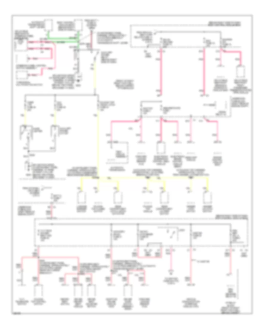
Power Distribution Wiring Diagram (2 of 4) for Cadillac XLR V 2007
List of elements for Power Distribution Wiring Diagram (2 of 4) for Cadillac XLR V 2007:
- (behind right side of dash) body control module (bcm)
- (in instrument panel harness, approximately 39 cm from blower motor processor breakout) s208
- (in instrument panel harness, approximately 4.0 cm from data link breakout) s231
- (not used)
- 4.4l
- 4.6l
- A12 c1
- A6 c3
- A7 c2
- A8 c2
- A8 c3
- Adaptive cruise module (acm)
- Automatic transmission shift lever
- B c1
- B11 c3
- B3 c3
- Batt 3 fuse 26 60a
- Btsi sol/col lock fuse 10 10a
- C1 c4
- Cd changer
- Clstr/hud fuse 26 15a
- D1 c3
- D10
- D6 c3
- D8 c4
- Data link connector (dlc)
- Deck lid close/park/ brk b fuse 32 10a
- Digital radio receiver
- Diode
- Dr locks fuse 15 15a
- Driver climate control seat module
- E10 c4
- E11 c3
- Exhaust flow control module
- F1 c1
- F19
- F6 c4
- From batt 1 fuse 33 (diagram 1 of 4)
- G19
- Head up display (hud)
- Hvac control module
- Hvac/ pwr snd fuse 29 10a
- I/p relay block (front of right front footwell, behind carpet)
- Inadv- ertent load control pcb relay
- Inside air temperature sensor
- Inside rearview mirror
- Instrument panel cluster (ipc)
- Interior lights fuse 17 10a
- Isrvm/ hvac fuse 25 10a
- Logic
- M10
- M18
- Passenger climate control seat module
- Pnk
- Prk/brk hold relay 47
- Radio
- Radio, s-band/ vics fuse 27 15a
- Rear compartment lid release/ close switch
- Rear fog/ aldl fuse 30 10a
- Rear object sensor control module
- Reverse lamp relay 6
- Rly ctrl
- Rpa/h/c seat/wipr relays fuse 14 10a
- Run/crank relay 7
- Stop lamp relay 24
- Stop/b/u/ lps fuse 5 15a
- To batt 5 fuse 7 (diagram 3 of 4)
- To gmlan devices fuse 1 (diagram 3 of 4)
- Traffic information receiver
- Tutd sw strg col sw fuse 28 2a
- Underhood fuse block (right rear of engine compt)
- W/ digital radio
- W/ information system 004
- W/s wash relay 36
- Wiper hi/lo relay 41
- Wiper on/off relay 45
- Wiper/ washer system
Power Distribution Wiring Diagram (3 of 4) for Cadillac XLR V 2007
List of elements for Power Distribution Wiring Diagram (3 of 4) for Cadillac XLR V 2007:
- (behind right side of dash) body control module (bcm)
- (front of right front footwell, behind carpet) i/p fuse block
- (in folding top harness, approximately 20 cm from breakout for c433) s333
- (in folding top harness, approximately 35 cm from header latched switch) s319
- (in instrument panel harness, approximately 12.0 cm from passenger's rear speaker breakout) s355
- (in instrument panel harness, approximately 14.5 cm from breakout to automatic transmission shift lever) s276
- (in instrument panel harness, approximately 14.5 cm from breakout to automatic transmission shift lever)
- (not used)
- 19 cm from memory seat switch) s393
- 4.6l
- A1 c4
- Abs/mrrtd/afs fuse 1 10a
- Acc/tcm fuse 3 10a
- Acca/driv dr sw fuse 21 10a
- Adaptive cruise module (acm)
- Automatic transmission
- Automatic transmission shift lever
- Aux pwr fuse 45 20a
- Auxiliary power outlet
- Auxiliary power relay (behind right side of dash)
- B10
- B12 c3
- B5 c3
- Batt 5 fuse 7 30a
- Body control module (bcm) (behind right side of dash)
- C10
- C13
- C400
- C5 c3
- C5 c4
- Cigar lighter
- Cigar ltr fuse 46 20a
- Crank relay 43
- D11
- D11 c3
- D12
- Driver door switch assembly (ddsa)
- Driver memory seat module
- Driver seat adjuster switch
- E10
- E11
- Ecm fuse 16 15a
- Electronic brake control module (ebcm)
- Electronic suspension control (esc) module
- Engine control module (ecm)
- F10
- F11
- F11 c2
- Folding top closed switch
- Folding top control switch
- Folding top module
- Folding top/ trunk latch fuse 44 15a
- Forward locking sensor (fls)
- Forward looking sensor (fls)
- From batt 1 fuse 33 (diagram 1 of 4)
- From rpa/h/c/ d seat/wipr relays fuse 14 (diagram 2 of 4)
- From stop/b/u/ c lps fuse 5 (diagram 2 of 4)
- G202
- Gmlan devices fuse 13 20a
- Header latch switch
- Header unlatch switch
- Headlamp module
- I/p relay block (front of right front footwell, behind carpet)
- Ign sw/ intr sensr fuse 23 10a
- Inflatable restraint front passenger presence system (pps) module
- Inflatable restraint sensing & diagnostic module (sdm)
- Inflatable restraints steering wheel module coil
- Logic
- Luggage barrier switch
- Memory seat switch
- Nca
- Onstar fuse 20 10a
- Pnk
- Prk, brk sol a fuse 8 20a
- Prk/ brk release relay 48
- Rear compartment lid open switch
- Rear compartment lid pulldown actuator
- S248 (in instrument panel harness, approximately 39.5 cm from inside rearview mirror breakout)
- S276
- Scmpsir sw fuse 18 10a
- Splice pack sp202 (in instrument panel harness, at base of right a pillar behind trim panel, grounded to g202)
- Steering wheel control switch assembly
- Tech module assembly
- Tilt/ telescope switch
- Tilt/tele sw/mem seat mod fuse 22 10a
- To ignition mode switch (4 of 4)
- Turn/signal multifunction switch
- Underhood fuse block (right rear of engine compt)
- Vehicle communication interface module (vcim)
- W/ onstar
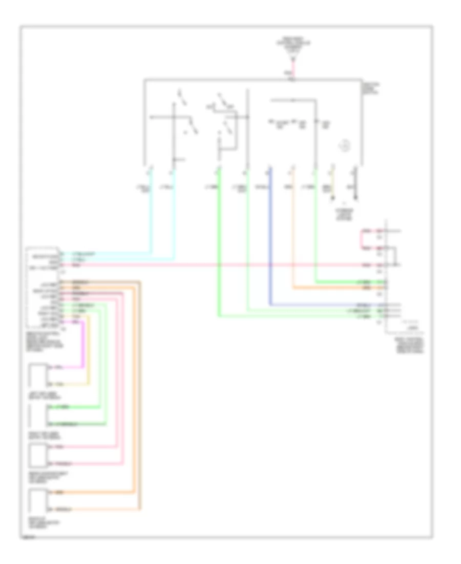
Power Distribution Wiring Diagram (4 of 4) for Cadillac XLR V 2007
List of elements for Power Distribution Wiring Diagram (4 of 4) for Cadillac XLR V 2007:
- Acc ind
- Back up sig
- Back-up keyless entry antenna
- Body control module (bcm) (behind right side of dash)
- From body control module (diagram 3 of 4)
- Gnd
- Ign 1 voltage
- Ign data sig
- Ignition mode switch
- Interior lights system
- Left keyless entry antenna
- Left sig
- Logic
- Low ref
- Off
- Off ind
- Pnk
- Rear compartment keyless entry antenna
- Remote control door lock receiver (rcdlr) (behind right side of dash)
- Right keyless entry antenna
- Right sig
- Sig
- Start ind
- Tan