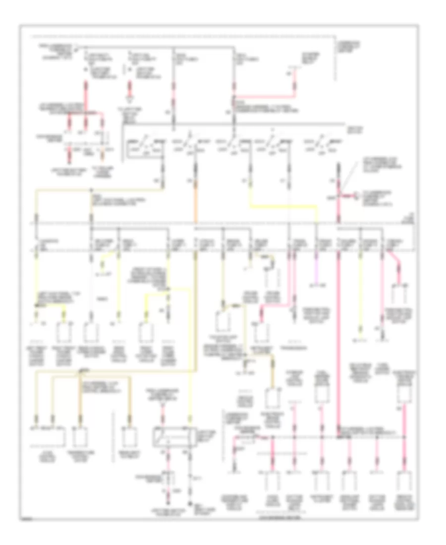
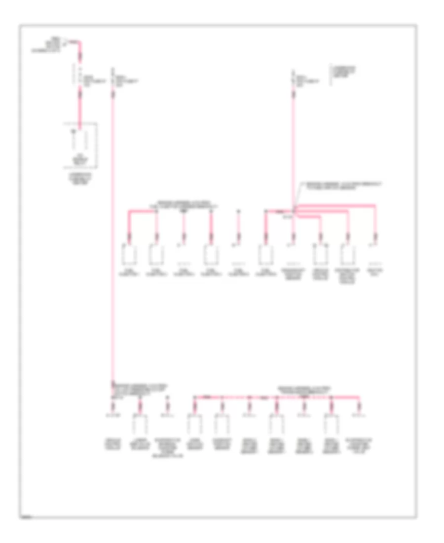
POWER DISTRIBUTION
Power Distribution Wiring Diagram (1 of 3) for Chevrolet Astro 1997

List of elements for Power Distribution Wiring Diagram (1 of 3) for Chevrolet Astro 1997:
- (engine harness, 24 cm from underhood fuse-relay center) s109
- (front of dash, 18 cm from fwd lamp harness breakout)
- (i/p harness, 17 cm from cluster breakout)
- (i/p harness, 2 cm from headlamp switch breakout) s211 red
- (i/p harness, 21 cm from heater a/c control breakout)
- (i/p harness, 4 cm from headlamp switch breakout)
- (i/p harness, 9 cm from cluster breakout) s220
- (left door harness, 4 cm from power door lock switch connector breakout)
- (left door harness, 6 cm from outside rearview mirror breakout)
- (power seat harness, 7 cm from left power seat breakout)
- (right door harness, 4 cm from power door lock switch breakout)
- (vanity mirror harness, 7 cm from left vanity mirror breakout) s237
- A/c comp mini fuse k11 10a
- A/c enable relay
- A/c maxi fuse m3 30a
- A12
- Abs maxi fuse m4 60a
- Audio alarm module
- Aux pwr fuse 7 25a
- Batt maxi fuse 7 50a
- Battery
- Blower motor resistor and relay pack
- C207
- C222
- Center dome lamp
- Center dome/reading lamps
- Cig ltr fuse 13 20a
- Cigarette lighter
- Convenience center
- Ctsy fuse 3 20a
- Data link connector
- Daytime running lamp diode
- Door lock control module
- Door lock relay
- Driver seat adjuster switch
- Drl fuse 15 10a
- Ecm-b mini fuse f11 20a
- Electronic brake control module
- Electronic variable orifice module
- From underhood a fuse-relay center above
- Front auxiliary power outlets
- Front dome/ reading lamps
- Fuel pump relay
- Fusible link
- G901 (right "a" pillar)
- G999 (left "d" pillar)
- Generator
- Headlamp and panel dimmer
- Headlamp and panel dimmer switch
- Horn mini fuse h11 20a
- Horn relay
- Hvac control module
- I/p compartment lamp
- I/p fuse block
- Illum fuse 14 10a
- Interior lamp control module
- Interior lights
- Interior lights system
- Left courtesy lamp
- Left door courtesy lamp
- Left power door lock switch
- Left vanity lamp
- Liftgate lock/latch module
- Lighting maxi fuse 8 40a
- Locks/ seats cb 30a
- Oil pressure switch and sender
- Outside rearview mirror switch
- Passenger seat adjuster switch
- Pk lps fuse 9 20a
- Radio
- Radio batt fuse 19 10a
- Rear auxiliary power outlet
- Rear defog mini fuse f9 30a
- Rear dome lamp
- Rear heat- a/c relay
- Red
- Relay center
- Remote control door lock receiver
- Right courtesy lamp
- Right door courtesy lamp
- Right power door lock switch
- Right stepwell lamp
- Right vanity lamp
- Rr heat a/c maxi fuse m2 30a
- S132
- S213
- S223
- S227
- S319
- S322 (left side of vehicle, 4 cm from side door harness breakout)
- S500
- S600
- Starter solenoid
- Steering fuse 21 10a
- Stop/haz fuse 1 20a
- Subwoofer amplifier
- Switch
- System
- Tcc/stoplamp switch
- To underhood fuse-relay center (diagram 2 of 3)
- To underhood fuse-relay center below
- Turn/ hazard switch
- Underhood fuse-
- Underhood fuse-relay center
- Upfitter battery power stud
- Vehicle control module
Power Distribution Wiring Diagram (2 of 3) for Chevrolet Astro 1997
List of elements for Power Distribution Wiring Diagram (2 of 3) for Chevrolet Astro 1997:
- (front of dash, 4 cm from bulkhead grommet, toward windshield washer motor) s134
- (i/p harness, 14 cm from heater a/c control breakout)
- (i/p harness, 2 cm from temperature control motor breakout) s303
- (i/p harness, 6 cm from connector at lower steering column)
- (left kick panel, 7 cm from park brake switch breakout) s305
- (not used)
- Acc
- Air bag fuse 10 10a
- Audio alarm module
- B10
- B17
- Brake fuse 18 10a
- C200
- C214
- Center (diagram 1 of 3)
- Compass and temperature display module
- Convenience center
- Crank fuse 8 10a
- Cruise control module
- Cruise control switch
- Cruise fuse 6 10a
- Daytime running lamps module
- Daytime running lamps relay
- E nca
- Electronic brake control module
- Electronic variable orifice module
- From underhood fuse-relay b
- From underhood fuse-relay center above
- Front pulse wiper/ washer switch
- Front wiper motor and module
- Fuel/ sender gauge module
- G201 (right side of dash)
- Gauges fuse 4 10a
- Headlamp and panel dimmer switch
- Htr-a/c fuse 12 20a
- Hvac control module
- I/p fuse block
- Ign-a maxi fuse 6 40a
- Ign-b maxi fuse 5 40a
- Ignition switch
- Inflatable restraint sensing diagnostic module
- Instrument cluster
- Interior lamp control module
- Left front power window master switch
- Lock
- Nca
- Off
- Park/neutral position and backup lamp switch
- Pnk
- Pnk (i/p harness, 4 cm from headlamp switch breakout) s213
- Pnk c207
- Radio
- Radio fuse 17 10a
- Rear heat- a/c relay
- Rear radio control module
- Rear window wiper/washer switch
- Red
- Remote control door lock receiver
- Right front power window master switch
- Rr wiper fuse 23 20a
- Run
- S108 (engine harness, 17 cm from underhood fuse-relay center)
- S111
- S114
- S203 (left kick panel, 4 cm from bulkhead connector)
- S205
- S224
- Start
- Starter enable relay
- Tcc/stoplamp switch
- Temperature control motor
- To trailer wiring harness
- To underhood fuse-relay center (diagram 3 of 3)
- To upfitter ignition relay below
- Trans fuse 20 10a
- Transmission
- Turn-b/u fuse 4 10a
- Turn/ hazard switch
- Underhood fuse-relay center
- Upfit-batt maxi fuse p8 30a
- Upfit-ign maxi fuse p7 30a
- Upfitter battery power stud
- Upfitter ignition power stud
- Upfitter ignition relay
- Vehicle control module
- Windows cb 30a
- Wiper fuse 11 25a
Power Distribution Wiring Diagram (3 of 3) for Chevrolet Astro 1997
List of elements for Power Distribution Wiring Diagram (3 of 3) for Chevrolet Astro 1997:
- (engine harness, 18 cm from breakout to mass airflow sensor)
- (engine harness, 6 cm from fuel injector harness breakout) s123
- (engine harness, 6 cm from transmission breakout) s126
- (engine harness, 9 cm from a/c low pressure cutoff switch breakout) s119
- A/c enable relay
- Bank 1 heated oxygen sensor 1
- Bank 1 heated oxygen sensor 2
- Bank 1 heated oxygen sensor 3
- Bank 2 heated oxygen sensor 1
- Camshaft position sensor
- Crankshaft position sensor
- Distributor ignition control module
- Ecm-1 mini fuse k7 20a
- Eng-1 mini fuse f7 20a
- Evaporative canister purge vent valve
- Evaporative emission canister purge solenoid valve
- From ignition d switch (diagram 2 of 3)
- Fuel injector 1
- Fuel injector 2
- Fuel injector 3
- Fuel injector 4
- Fuel injector 5
- Fuel injector 6
- Ign-e mini fuse m7 10a
- Ignition coil
- Linear egr valve solenoid
- Mass air flow sensor
- Pnk
- S116
- Underhood fuse-relay center
- Vehicle control module