POWER DISTRIBUTION
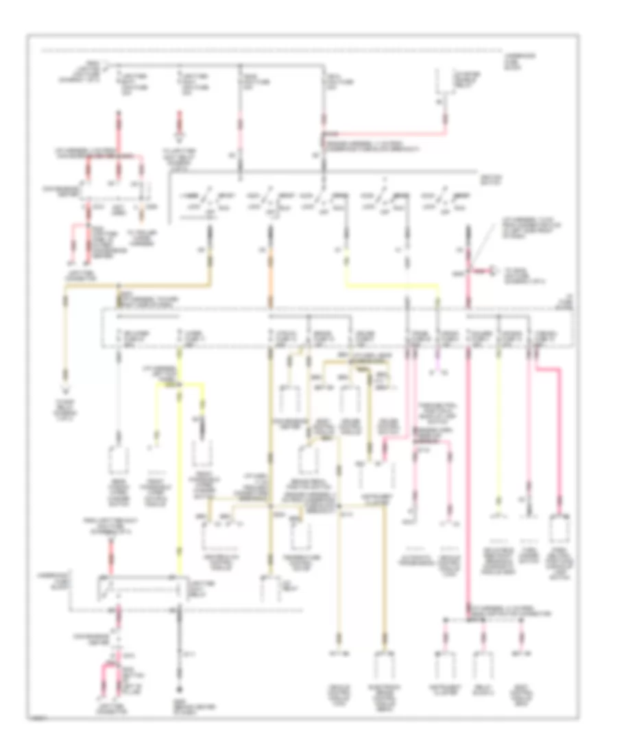
Power Distribution Wiring Diagram (1 of 3) for Chevrolet Astro 2000

List of elements for Power Distribution Wiring Diagram (1 of 3) for Chevrolet Astro 2000:
- (i/p harness, 10 cm from bcm connectors breakout)
- (i/p harness, 17 cm from instrument cluster conn breakout)
- (i/p harness, left kick panel)
- (i/p harness, lower half of steering column) s209 red
- (i/p harness, right kick panel)
- (left door harness, 17 cm from power window switch breakout)
- (power seat harness, 7 cm from left power seat breakout)
- (right door harness, 6 cm from power door lock switch breakout)
- A/c comp mini fuse 10a
- A/c enable relay
- A/c relay
- A12
- Abs maxi fuse 60a
- Atc mini fuse 20a
- Automatic transfer case shift control module
- Aux pwr fuse 7 25a
- Batt maxi fuse 50a
- Battery
- Blower motor resistor & relay pack
- Body control module (bcm)
- Brake pedal position switch
- C222
- C224
- Cig ltr fuse 13 20a
- Cigar lighter
- Convenience center
- Ctsy fuse 3 20a
- Data link connector (dlc)
- Daytime running lamps (drl) relay
- Door lock relay
- Driver seat adjuster switch
- Ecm-b mini fuse 20a
- Electronic brake control module (ebcm)
- From abs maxi fuse a (diagram 1 of 3)
- Front auxiliary power outlets
- Frt hvac fuse 30a
- Fuel pump relay
- Fusible link
- G901 (right front "a" pillar, above door jamb switch)
- G999 (upper half of left "d" pillar)
- Generator
- Headlamp & panel dimmer switch
- Headlamp dimmer switch
- Headlamps relay
- Heater & a/c control module
- Horn mini fuse 20a
- Horn relay
- Htd mir/ rr defog mini fuse 40a
- I/p fuse block
- Inadvertent power relay
- Instrument cluster
- Left power door lock switch
- Liftgate lock/ unlock release switch
- Lighting maxi fuse 40a
- Nca
- Outside rearview mirror control switch
- Passenger seat adjuster switch
- Passenger van
- Pk lps fuse 9 20a
- Pwr accy cb 30a
- Pwr mir fuse 21 5a
- Radio
- Radio batt fuse 19 10a
- Rap fuse 40a
- Rear auxiliary power outlet
- Red
- Relay block 1
- Relay block 2
- Remote control door lock receiver
- Right power door lock switch
- Rr htr-a/c maxi fuse 30a
- S121
- S133
- S221
- S223
- S227
- S260
- S319
- S322 (left "b" pillar, 4 cm from break- out toward top of vehicle)
- S500
- S600
- Starter solenoid
- Stop/haz fuse 1 20a
- Subwoofer amplifier
- Tbc fuse 15 10a
- To illum fuse 14 (diagram 3 of 3)
- To lighting maxi-fuse (diagram 1 0f 3)
- To rap relay (diagram 3 of 3)
- To upfitter-batt maxi fuse (diagram 2 of 3)
- Turn/ hazard switch
- Underhood fuse block
- Vehicle control module (vcm)
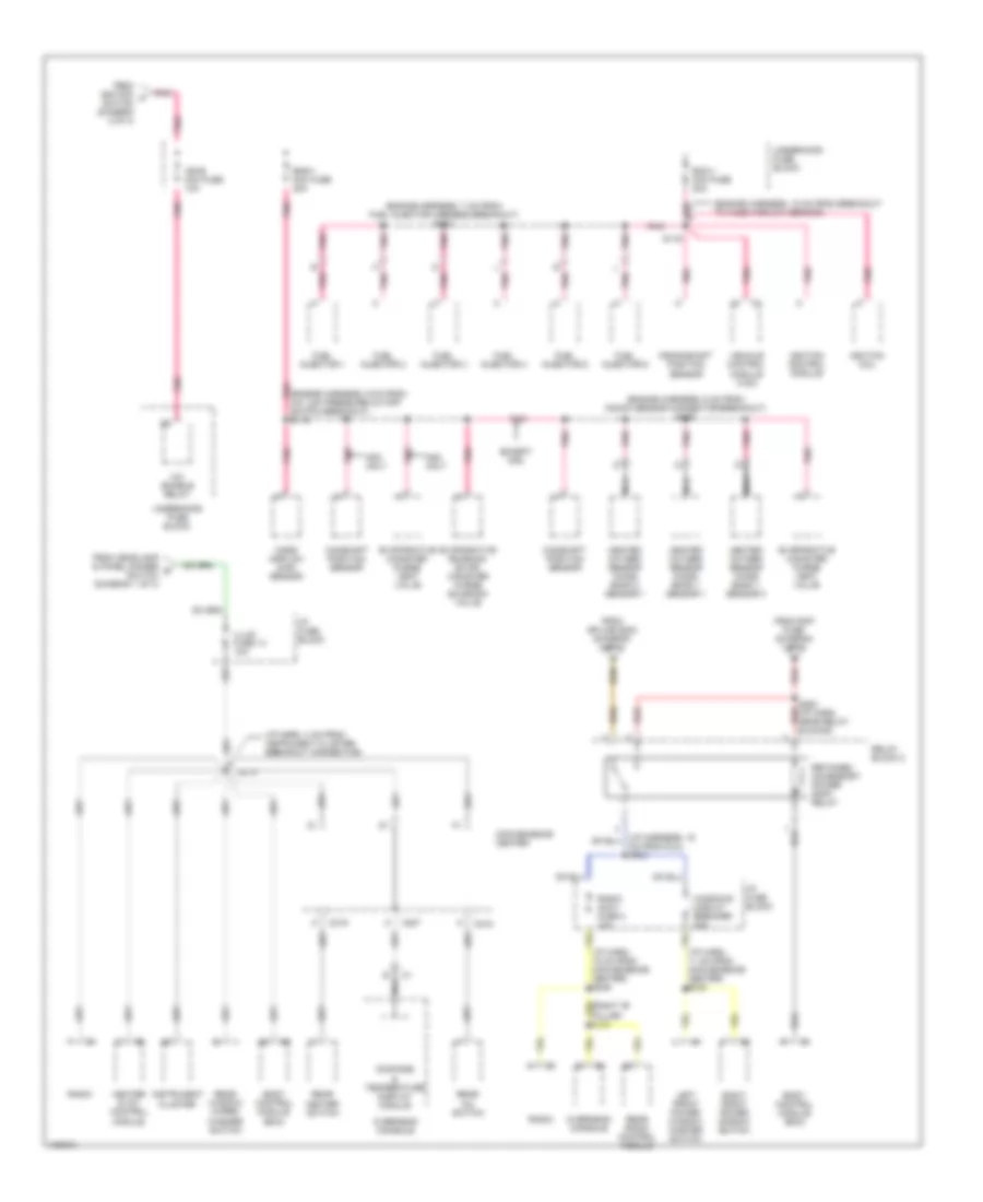
Power Distribution Wiring Diagram (2 of 3) for Chevrolet Astro 2000
List of elements for Power Distribution Wiring Diagram (2 of 3) for Chevrolet Astro 2000:
- (engine harness, 11 cm from underhood fuse block breakout)
- (engine harness, 4 cm from underhood fuse block breakout)
- (i/p harn, 17 cm from bcm connectors breakout)
- (i/p harness, 3 cm from convenience center) s303
- (i/p harness, 7.5 cm from connector c100 (in left side front of dash)
- (i/p harness, left kick panel) s324
- (not used)
- A/c relay
- A13
- Acc
- Air bag fuse 10 10a
- Automatic transmission
- B10
- Body control module
- Body control module (bcm)
- Brake fuse 18 10a
- Brake pedal position switch
- C206
- C210
- Convenience center
- Crank fuse 8 10a
- Cruise control module
- Cruise control switch
- Cruise fuse 6 10a
- Electronic brake control module (ebcm)
- From lighting c
- From upfitter-accy maxi fuse (diagram 2 of 3)
- Front windshield wiper motor & module
- Front windshield wiper/ washer switch
- G206 (behind center of dash)
- Gauges fuse 4 10a
- Heater & a/c control module
- Htr-a/c fuse 12 20a
- I/p fuse block
- Ign-a maxi fuse 40a
- Ign-b maxi fuse 40a
- Ignition switch
- Inflatable restraint sensing & diagnostic module (sdm)
- Instrument cluster
- Left "b" pillar)
- Lock
- Maxi fuse (diagram 1 of 3)
- Nca
- Off
- Park/ neutral position & & back-up lamp switch
- Park/neutral position & back-up lamp switch
- Pnk
- Pnk (engine harn, near maf sensor)
- Pnk (i/p harness, 41 cm from headlamp switch connector) s213
- Rear window wiper/ washer switch
- Red
- Relay block 2
- Rr wiper fuse 23 20a
- Run
- S108
- S111
- S114
- S115 pnk
- S201
- S203 (i/p harness, toward right side of dash)
- S205
- S224
- S240 (upfitter harn, 30 red cm from convenience center)
- S242 (bottom of pnk
- Start
- Starter enable relay
- Temperature control motor
- To ign-e mini fuse (diagram 3 of 3)
- To rap relay (diagram 3 of 3)
- To trailer wiring harness
- To upfitter accy relay (diagram 2 of 3)
- Trans fuse 20 10a
- Turn-b/u fuse 16 20a
- Turn/ hazard switch
- Underhood fuse block
- Upfitter accy relay
- Upfitter connector
- Upfitter- accy maxi fuse 30a
- Upfitter- batt maxi fuse 30a
- Vehicle control module (vcm)
- Wiper fuse 17 25a
Power Distribution Wiring Diagram (3 of 3) for Chevrolet Astro 2000
List of elements for Power Distribution Wiring Diagram (3 of 3) for Chevrolet Astro 2000:
- (engine harness, 18 cm from breakout to mass airflow sensor)
- (engine harness, 6 cm from knock sensor connector breakout) s126
- (engine harness, 7 cm from fuel injector harness breakout) s123
- (engine harness, 9 cm from a/c low pressure cutoff switch breakout) s119
- (i/p harn, 11 cm from convenience center) s305
- (i/p harn, 15 cm from convenience center) s246
- (i/p harn, 4 cm from instrument cluster breakout connector)
- A/c enable relay
- Body control module (bcm)
- C207
- C218
- C219
- Camshaft position sensor
- Cm from dlc) s253
- Compass & temperature display module
- Convenience center
- Crankshaft position sensor
- Ecm-1 mini fuse 20a
- Eng-1 mini fuse 20a
- Evaporative canister purge vent valve
- Evaporative emission (evap) canister purge solenoid valve
- Except nm2
- From headlamp & panel dimmer d switch (diagram 1 of 3)
- From ignition f switch (diagram 2 of 3)
- From rap fuse (diagram 1 of 3)
- From splice s203 (diagram 2 of 3)
- Fuel injector 1
- Fuel injector 2
- Fuel injector 3
- Fuel injector 4
- Fuel injector 5
- Fuel injector 6
- Heated oxygen sensor (ho2s) bank 1 sensor 1
- Heated oxygen sensor (ho2s) bank 1 sensor 3
- Heated oxygen sensor (ho2s) bank 2 sensor 1
- Heater & a/c control module
- I/p fuse block
- Ign-e mini fuse 10a
- Ignition coil
- Ignition control module
- Illum fuse 14 10a
- Instrument cluster
- Left front power window master switch
- Mass airflow (maf) sensor
- Nca
- Nm2 only
- Overhead console
- Pnk
- Radio
- Radio accy fuse 2 10a
- Rear a/c switch
- Rear heater switch
- Rear radio control module
- Rear window wiper/ washer switch
- Red
- Relay block 2
- Retained accessory power (rap) relay
- Right front power window switch
- S116
- S219
- S252 (i/p harn, near relay red blocks)
- Underhood fuse block
- Vehicle control module (vcm)
- Windows circuit breaker 30a