POWER DISTRIBUTION
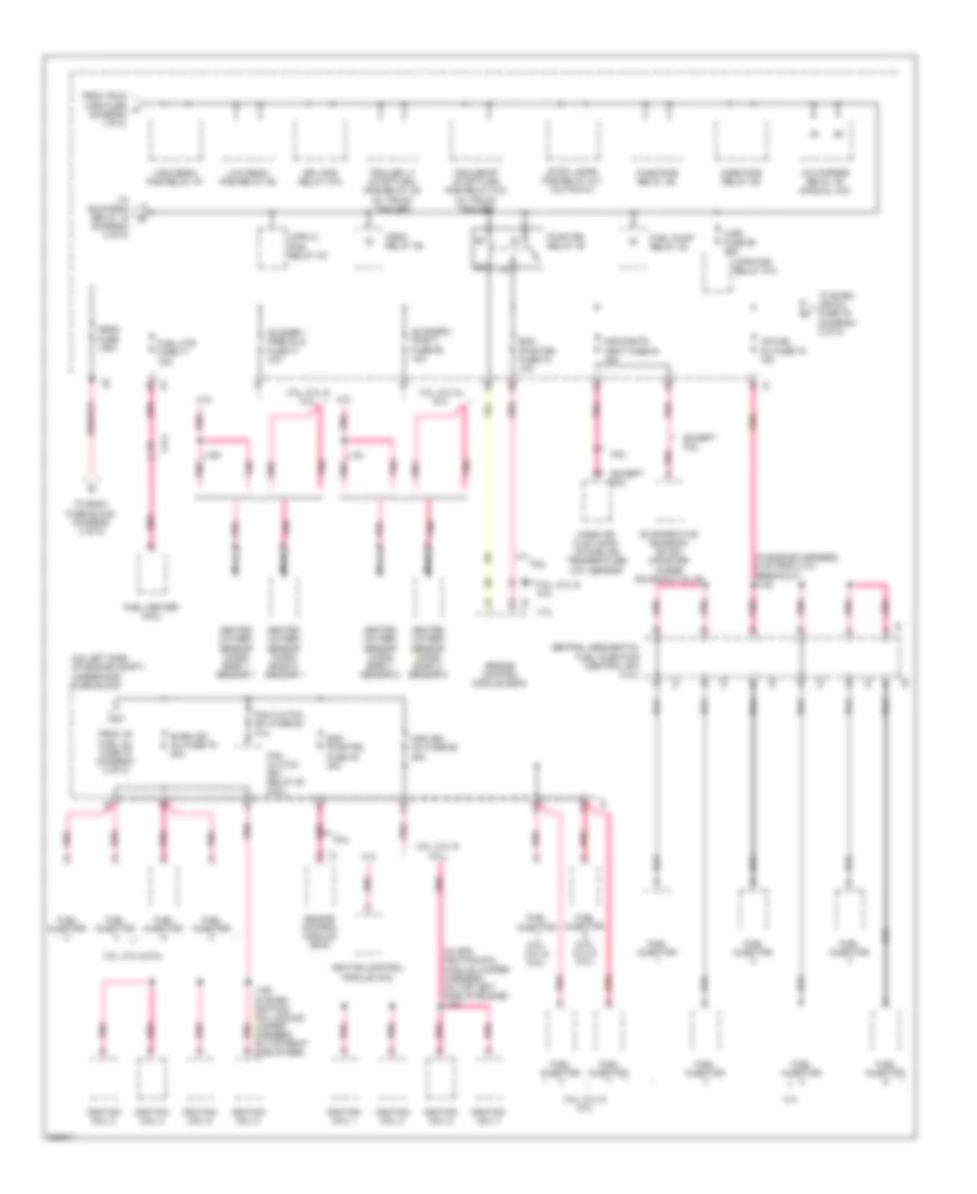
Power Distribution Wiring Diagram (1 of 5) for Chevrolet Chevy Express G1500 2011

List of elements for Power Distribution Wiring Diagram (1 of 5) for Chevrolet Chevy Express G1500 2011:
- (on left side of engine compt) underhood fuse block
- 30a
- 4.3l/ 5.3l
- 4.8l & 6.0l
- 50a
- 6.6l
- Abs mdl fuse 2 40a
- Abs mtr fuse 1 50a
- Automatic transmission
- Aux pwr outlet fuse 25 20a
- Auxiliary battery
- Auxiliary generator
- Battery
- Bcm 1 fuse 59 10a
- Bcm 2 fuse 58 15a
- Bcm 3 fuse 26 10a
- Bcm 4 fuse 9 10a
- Bcm 5 fuse 7 10a
- Bcm 6 fuse 72 10a
- Bcm 7 fuse 8 10a
- Blower motor resistor
- Body control module (bcm)
- Body fuse block (under left front seat)
- Center console 1 accessory power outlet
- Center console 2 accessory power outlet
- Cigar lighter
- Cnstr vent sol fuse 56 10a
- Control solenoid valve assembly
- Coolant heater (6.6l)
- Cutaway, ambulance &
- Data link connector (dlc)
- Ecm batt fuse 19 10a
- Electrical provisions
- Electronic brake control module (ebcm)
- Engine control module (ecm)
- Evaporative emission (evap) canister vent solenoid valve
- Except 6.6l
- Fcsm batt fuse 36 20a
- Foh mdl fuse 35 15a
- Frt blwr fuse 74 40a
- Fuel pump flow control module (5.3l)
- Fuse 28
- Fusible link 1
- Fusible link 2
- Fusible link 3
- Fusible link 4
- Fusible link 5 (w/ dual generator 145a)
- G302 (behind left kick panel)
- G304 (behind right kick panel)
- Generator
- Glow plug control module (gpcm)
- Instrument panel cluster (ipc) (w/ odometer security wiring provision (seo))
- Intake air heater (iah)
- J247
- J249
- Ltr/dlc fuse 73 20a
- Nca
- Reading lamps
- Red
- Rv upfitters
- Seo fuse 27 10a
- Starter motor
- Tcm batt fuse 32 10a
- To cmps fuse 19 (diagram 4 of 5)
- To high beam pcb relay k7 (diagram 2 of 5)
- To run relay k1 (diagram 4 of 5)
- Trailer connector
- Transmission control module (tcm)
- Trlr wrg fuse 11 30a
- Trlr wrg fuse 42 30a
- Underhood junction block
- Upfitter aux 2
- Upfitter provisional
- Upftr aux 2 relay k4 (cutaway, ambulance & rv upfitters w/ multiple interior reading lamps electrical provisions)
- W/ 4 speed a/t
- W/ 6 speed a/t
- W/ active brake control
- W/ cigar lighter
- W/ cutaway upfitter
- W/ multiple interior reading lamps
- W/ rv upfitter
- W/ truck trailer
- W/o active brake control
- W/o cigar lighter
- X101
- X174
- X222
- X321
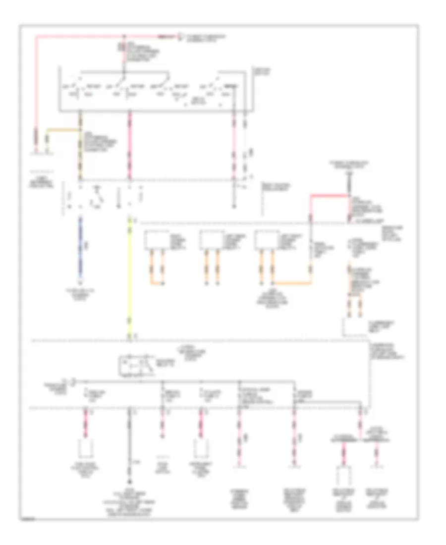
Power Distribution Wiring Diagram (2 of 5) for Chevrolet Chevy Express G1500 2011
List of elements for Power Distribution Wiring Diagram (2 of 5) for Chevrolet Chevy Express G1500 2011:
- (diagram 3 of 5)
- (in engine harness, 5 cm from x101 breakout) j120
- (in odd ignition/coil module jumper harness, on top left side of engine) j184
- (on left side of engine compt) underhood fuse block
- 4.3l
- 4.8l, 5.3l & 6.0l
- 6.6l
- A/c cmprsr relay 40 (manual a/c)
- Central sequential fuel injection (central sfi) (4.3l)
- Crnk relay 39
- Drl pcb relay k19
- Ecm pwr/trn fuse 45 30a
- Ecm pwr/trn fuse 78 10a
- Engine control module (ecm)
- Evaporative emission (evap) canister purge solenoid valve
- Even ign inj fuse 79 20a
- Except 6.6l
- Fan clutch (ev) relay 50 (6.6l)
- Fan clutch (ev) fuse 63 10a
- From trlr wrg fuse a (diagram 1 of 5)
- From v6 fuel inj fuse 75 (diagram 2 of 5)
- Fuel heater (6.6l)
- Fuel htr fuse 71 15a
- Fuel injector
- Fuel injector (4.8l, 5.3l & 6.0l)
- Fuel pump relay 38
- Heated oxygen sensor (ho2s) bank 1 sensor 1
- Heated oxygen sensor (ho2s) bank 1 sensor 2
- Heated oxygen sensor (ho2s) bank 2 sensor 1
- Heated oxygen sensor (ho2s) bank 2 sensor 2
- High beam pcb relay k7
- Horn pcb relay k5
- Ignition coil 1
- Ignition coil 2
- Ignition coil 3
- Ignition coil 4
- Ignition coil 5
- Ignition coil 6
- Ignition coil 7
- Ignition coil 8
- Ignition control module (icm)
- J150
- J151
- J185 (in even ignition/ coil module jumper harness, on top right side of eng)
- Low beam pcb relay k6
- Maf/cnstr vent fuse 64 15a
- Mass air flow (maf)/ intake air temperature (iat) sensor
- Mega fuse 125a
- Nca
- O2 snsr 1 (pre)/cls fuse 77 10a
- O2 snsr 2 (post) fuse 62 10a
- Odd ign/ inj fuse 65 20a
- Pnk
- Pwr/trn relay 49
- Stop lamps pcb relay k11 (cutaway)
- To body fuse block (diagram 4 of 5)
- To even ign/inj fuse 79 (diagram 2 of 5)
- To run/crnk relay 15 d
- Trailer lt stop/turn pcb relay k9 (w/ truck trailer)
- Trailer rt stop/turn pcb relay k18 (w/ truck trailer)
- V6 fuel inj fuse 75 15a
- Wash pcb relay k5
- Wpr fuse 55 25a
- Wpr h1 pcb relay k3
- Wpr pcb relay k13
- X174
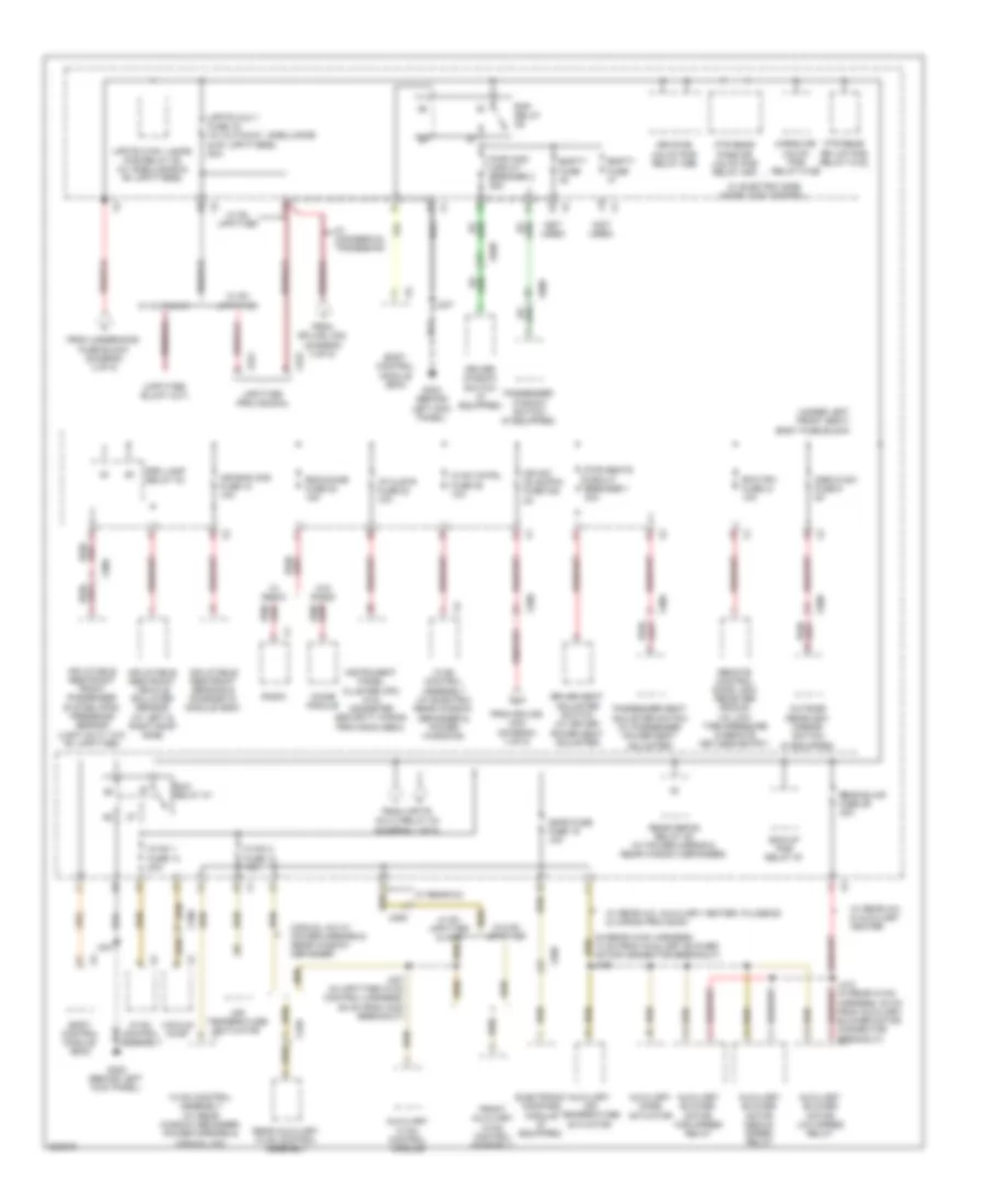
Power Distribution Wiring Diagram (3 of 5) for Chevrolet Chevy Express G1500 2011
List of elements for Power Distribution Wiring Diagram (3 of 5) for Chevrolet Chevy Express G1500 2011:
- (in prp/uf2 harness, 7 cm from breakout for rear fuse block) j312
- Acc
- Air bag fuse 28 10a
- Body control module (bcm)
- Brk sw fuse 13 10a
- Dome fluorescent work lamps fuse 2 10a
- Fluorescent work lamp relay
- From mega fuse (diagram 2 of 5)
- Fscm ign fuse 6 10a
- Fuel pump flow control module (5.3l)
- G102 (4.3l: right rear of engine) (4.8l/5.3l/6.0l: on left rear of engine) (6.6l: left front lower side of engine block)
- Ign
- Ignition switch
- Inflatable restraint i/p module disable switch
- Inflatable restraint i/p module indicator
- Inflatable restraint sensing & diagnostic module (sdm)
- Instrument panel cluster (ipc)
- Ip clstr fuse 10 10a
- J102
- J203 (in steering column harness, 27 cm from x200 connector)
- J205 (in steering column harness, 30 cm from x200 connector)
- J302 (in prp/uf2 harness, 15 cm from rear fuse block)
- J303 (in prp/uf2 harness, 8 cm from rear fuse block)
- Key-in switch
- Left front access panel relay 5
- Left rear access panel relay 1
- Off
- Panel actuator fuse 3 45a
- Pnk
- Rear fuse block (on left "b" pillar)
- Red
- Right access panel relay 6
- Run
- Run/crnk relay 15
- Start
- Steering wheel speed/ position sensor
- Stop lamp switch
- Str/whl snsr fuse 29 (w/ active brake control) 10a
- Theft deterrent module (tdm)
- To body fuse block (diagram 4 of 5)
- To splice j115 (diagram 5 of 5)
- To trans fuse (diagram 5 of 5)
- Underhood fuse block (on left side of engine compt)
- W/ cargo lamp
- W/ manual suppression
- W/o rv upfitter & manual suppression
- X100
- X200
- X318
Power Distribution Wiring Diagram (4 of 5) for Chevrolet Chevy Express G1500 2011
List of elements for Power Distribution Wiring Diagram (4 of 5) for Chevrolet Chevy Express G1500 2011:
- (in rear hvac harness, 13 cm from auxiliary blower motor connector breakout) j405
- (not used)
- (under left front seat) body fuse block
- Air bag aos fuse 10 10a
- Air temperature actuator
- Auxiliary air temperature actuator
- Auxiliary blower motor high speed relay
- Auxiliary blower motor low speed relay
- Auxiliary blower motor medium speed relay
- Auxiliary hvac control module
- Auxiliary mode actuator
- Bck/up pcb relay k7
- Body control module (bcm)
- Cargo dr unlck pcb relay k10b
- Chime module
- Cmps fuse fuse 19 10a
- Driver seat adjuster switch (w/ driver power seat adjuster)
- Driver window switch (if equipped)
- Drvr dr unlck pcb relay k9b
- Electronic compass module (if equipped)
- Empty fuse
- From splice j203 (diagram 3 of 5)
- From splice j302 (diagram 3 of 5)
- From underhood fuse block (diagram 2 of 5)
- From upftr aux 2 relay k4 (diagram 1 of 5)
- Front auxiliary hvac control assembly
- Ftr rear dr lck pcb relay k10a
- Ftr rear pass dr unlck pcb relay k9a
- G302 (behind left kick panel)
- Hvac 1 fuse 14 20a
- Hvac 2 fuse 13 10a
- Hvac cntrl fuse 25 10a
- Hvac control assembly
- Hvac control assembly (w/ electric rear window defogger & power windows)
- Hvac control assembly (w/ rear window defogger, power mirrors & manual a/c)
- I/p clstr fuse 23 10a
- Ign sw (dlis)/pk3 fuse f22 2a
- Inflatable restraint front passenger system (pps) presence sensor (light duty w/o rv upfitter)
- Inflatable restraint sensing & diagnostic module (sdm)
- Inflatable restraint vehicle rollover sensor (w/ left & right roof side)
- Instrument panel cluster (ipc) (w/o odometer security wiring provision (seo))
- J247
- J307 (in upfitter hvac control harness, 88 cm from x303 breakout)
- J412 (in rear hvac harness, 20 cm from auxiliary blower motor connector breakout)
- Manual a/c w/ power mirrors & rear window defogger
- Osrvm sw fuse 9 5a
- Outside rearview mirror switch (if equipped)
- Passenger seat adjuster switch (w/ passenger power seat adjuster)
- Passenger window switch (if equipped)
- Prk lamp relay k3
- Pwr seats circuit breaker 1 30a
- Pwr wdo circuit breaker 2 25a
- Radio
- Rap relay k6
- Rdo/chime fuse 20 15a
- Rear auxiliary hvac control assembly
- Rear blwr fuse 29 30a
- Rear defog relay k5 (w/ power mirror & rear window defogger)
- Remote control door lock receiver (rcdlr) (w/ low tire pressure & remote keyless entry)
- Rfa/tpm fuse 21 10a
- Run relay k1
- Upfitter provisional
- Upftr aux 1 fuse 16 (w/ cutaway, ambulance & rv upfitters) 50a
- Upftr ctsy lamps pcb relay k8 (w/ ambulance & rv upfitters)
- Vacuum pump
- W/ commercial tradesman
- W/ cutaway
- W/ electric side door lock control
- W/ radio
- W/ rear a/c
- W/ rear a/c & auxiliary heater
- W/ rear a/c, auxiliary heater, plumbing & wiring provision
- W/ rv upfitter
- W/ rv upfitter & 3406
- W/o radio
- W/o rv upfitter
- X100
- X200
- X205
- X222
- X306
- X321
- X420
- X500
- X600
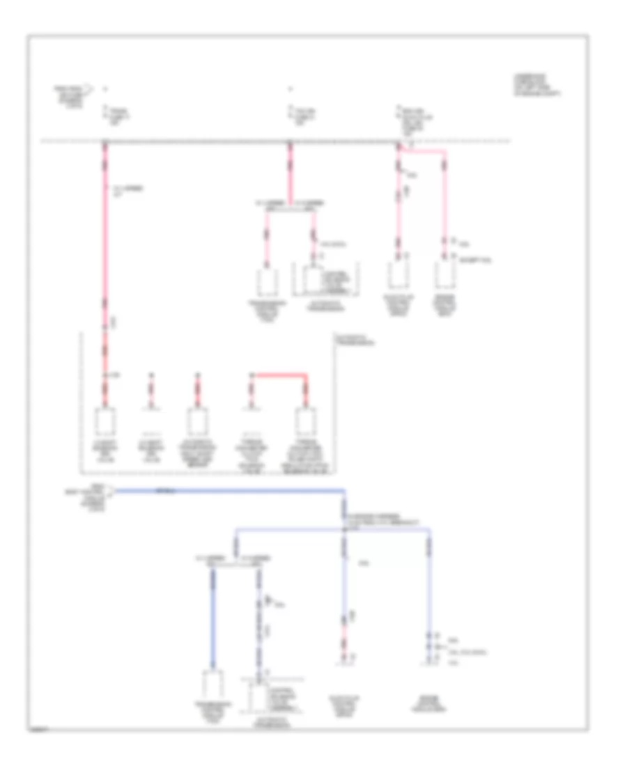
Power Distribution Wiring Diagram (5 of 5) for Chevrolet Chevy Express G1500 2011
List of elements for Power Distribution Wiring Diagram (5 of 5) for Chevrolet Chevy Express G1500 2011:
- (in engine harness, 15 cm from x101 breakout) j115
- 1-2 shift solenoid (ss) valve
- 2-3 shift solenoid (ss) valve
- 4.3l
- 4.8l & 6.0l
- 4.8l, 5.3l & 6.0l
- 6.6l
- Automatic transmission
- Automatic transmission input shaft speed (iss) sensor
- Control solenoid valve assembly
- Ecm ign/ glow plug mdl ign fuse 30 15a
- Engine control module (ecm)
- Except 6.6l
- From body control h module (diagram 3 of 5)
- From fscm j ign fuse (diagram 3 of 5)
- Glow plug control module (gpcm)
- J135
- Pnk
- Red
- Tcm ign fuse 31 15a
- Torque converter clutch (tcc) pulse width modulation (pwm) solenoid valve
- Torque converter clutch (tcc) solenoid valve
- Trans fuse 17 15a
- Transmission control module (tcm)
- Underhood fuse block (on left side of engine compt)
- W/ 4 speed a/t
- W/ 6 speed a/t
- X101
- X107
- X174
- X175