POWER DISTRIBUTION
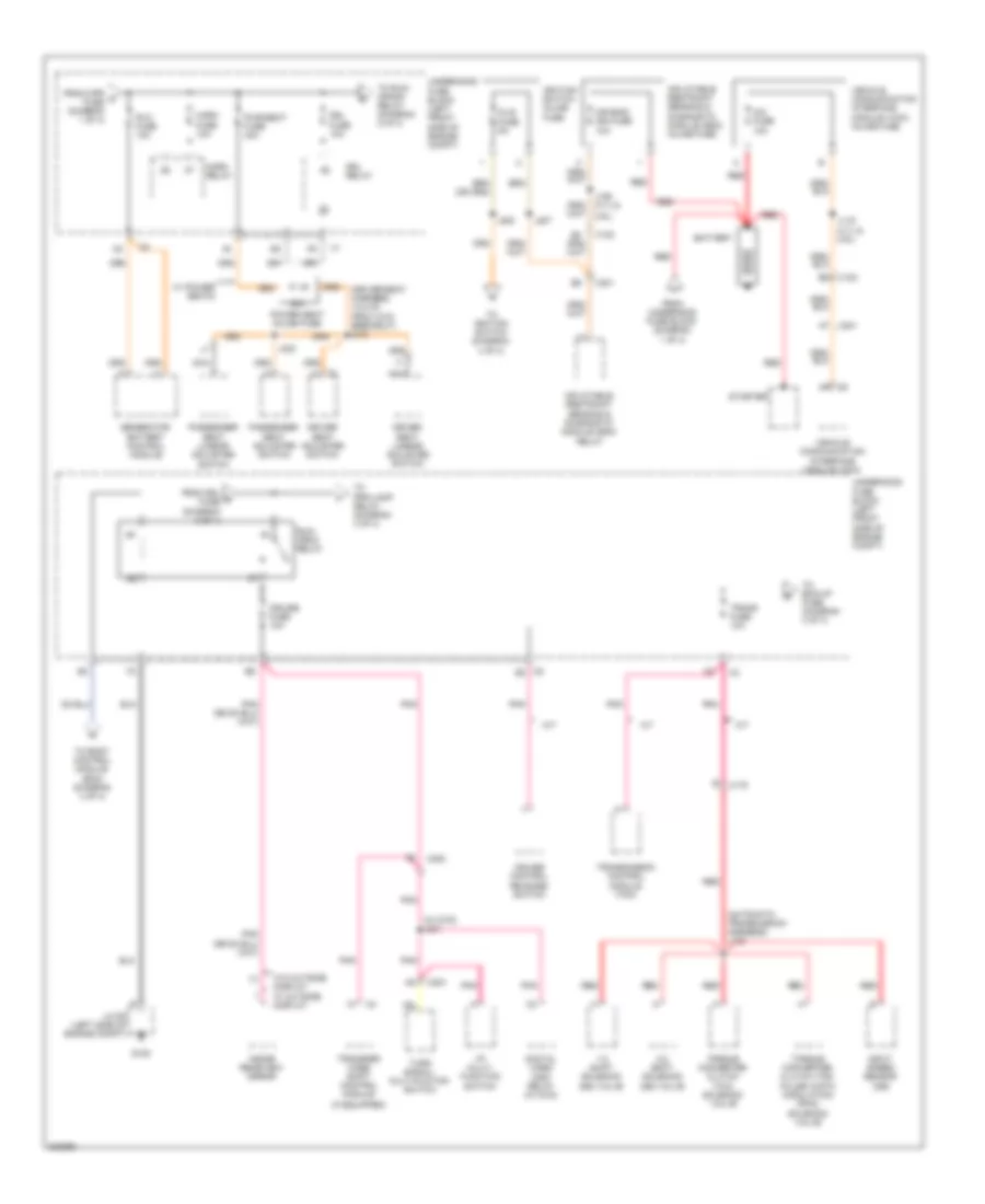
Power Distribution Wiring Diagram (1 of 4) for Chevrolet Colorado 2012

List of elements for Power Distribution Wiring Diagram (1 of 4) for Chevrolet Colorado 2012:
- (body harness, 4 cm from accelerator pedal position switch breakout)
- (engine harness, 18cm front generator battery control module) j107
- (engine harness, 3cm from breakout fuse block) j108
- (if equipped)
- (left front side of engine compt) underhood fuse block
- (not used)
- (right side of engine compt) jx106
- 50a
- A/c fuse 10a
- A10
- A11
- A26
- Abs 1 fuse 30a
- Abs 2 fuse 40a
- Aux pwr 1 fuse 20a
- Aux pwr 2 fuse 20a
- B10
- B11
- Battery (diagram 2 of 4)
- Blower motor
- Blwr fuse 30a
- Body control module (bcm)
- Clstr fuse 10a
- Cnstr vent fuse 10a
- Crew cab w/ power windows
- Data link connector (dlc)
- Digital radio receiver
- Digital video disc relay (w/ dvd)
- Door unlock relay
- Dr/lck fuse 20a
- Driver door lock/ window switch
- Driver heated seat module
- Driver seat lumbar adjuster switch
- E red
- Electronic brake control module (ebcm)
- Engine control module (ecm)
- Evaporative emission (evap) canister vent solenoid valve
- F10
- F12
- Fog/ lamp relay
- Fog/lamp fuse 15a
- From a aux pwr 1 fuse (diagram 1 of 4)
- From b trn/hazrd rear fuse (diagram 1 of 4)
- Fscm fuse 20a
- Fuel pump flow control module
- Fuse 30a
- Fuse 5a
- Fusible link 1
- G106
- Generator
- Hdlp relay
- Htd/seat fuse 20a
- Hvac control module
- I/p 1 accessory power outlet
- I/p 2 accessory power outlet
- Ign 3 hvac relay
- Inline fuse digital video disc (dvd) (w/ dvd)
- Inline fuse trailer connector (if equipped)
- Instrument panel cluster (ipc)
- J200
- J302
- J332 (w/ dvd)
- J510
- Left rear window switch
- Mega fuse 125a
- Nca
- Passenger door lock/ window switch
- Passenger heated seat module
- Passenger seat lumbar adjuster switch (if equipped)
- Pcm b fuse 10a
- Pwr/ wndw fuse 30a
- Pwr/trn relay
- Radio
- Rap relay
- Rdo fuse 15a
- Red
- Regular, extended cab w/ power windows
- Right rear window switch
- S/roof fuse 20a
- Secondary air injection (air) pump fuse block (if equipped)
- Secondary air injection (air) pump relay
- Steering wheel position sensor
- Stop fuse 20a
- Strtr fuse 30a
- Strtr relay
- Tbc fuse 10a
- Tccm fuse 10a
- Tcm fuse 10a
- To dr/lck fuse (diagram 1 of 4)
- To rap relay (diagram 1 of 4)
- To rvc fuse (diagram 2 of 4)
- Trailer connector
- Transfer case shift control module (if equipped)
- Transmission control module (tcm) (if equipped)
- Trn/ hazrd frt fuse 15a
- Trn/ hazrd rear fuse 15a
- Turn signal/ multi- function switch
- Underhood fuse block (left front side of engine compt)
- Vses fuse 10a
- Vses/ stop relay
- W/ electric side door lock control
- W/o electric side door lock control
- Windshield wiper/washer switch
- Wpr fuse 25a
- Wpr relay
- Wsw fuse 10a
- X102
- X125
- X200
- X201
- X204
- X700
- X800
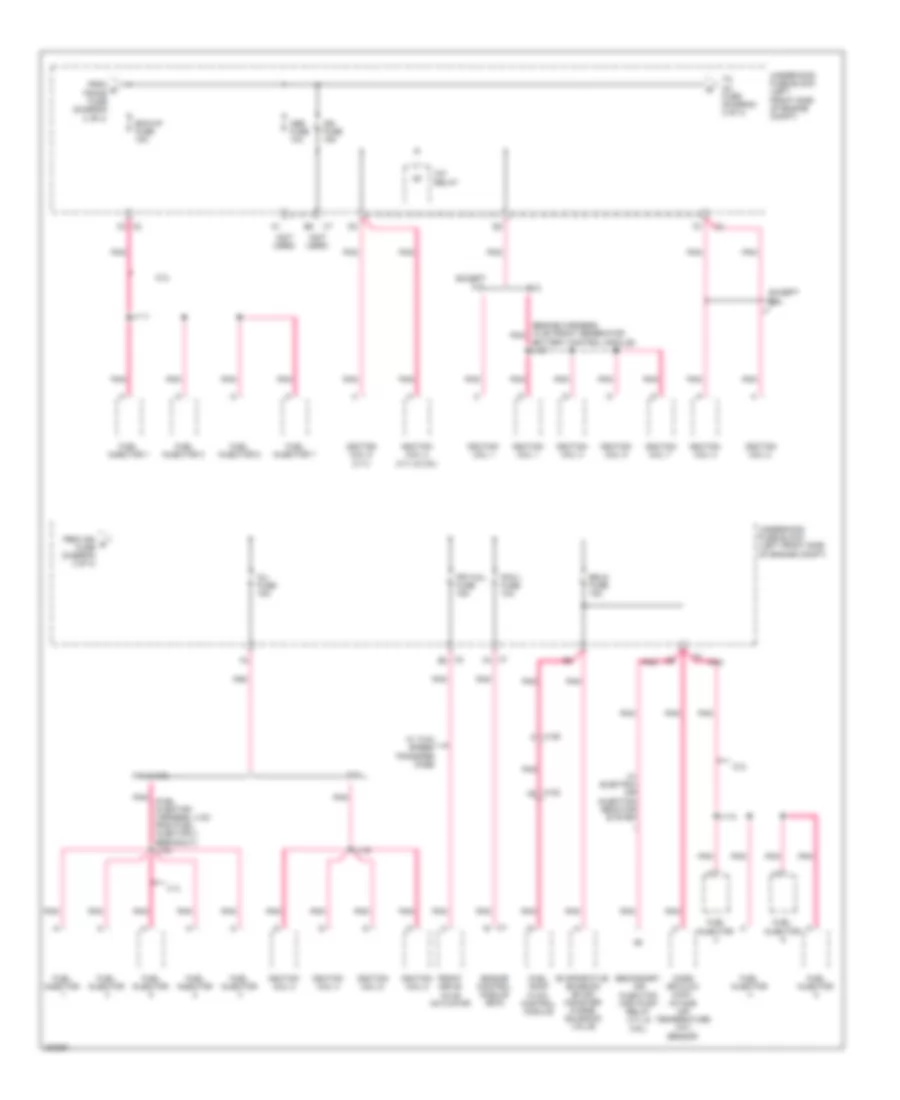
Power Distribution Wiring Diagram (2 of 4) for Chevrolet Colorado 2012
List of elements for Power Distribution Wiring Diagram (2 of 4) for Chevrolet Colorado 2012:
- (automatic transmission harness) j133
- (driver seat harness, 12.5 cm from x319 breakout) j312
- (if equipped)
- (iss)
- (w/ dvd) j331
- 1-2 shift solenoid (ss) valve
- 2-3 shift solenoid (ss) valve
- 20a
- A/t
- Air bag/ ign fuse 10a
- B5 x102
- Battery
- Cim fuse 10a
- Cruise control release switch
- Cruise fuse 10a
- Digital video disc relay (w/ dvd)
- Dlis fuse 5a
- Driver seat adjuster switch
- Driver seat lumbar adjuster switch
- Drl fuse 10a
- Drl relay
- From drl d fuse (diagram 2 of 4)
- From underhood fuse block (diagram 1 of 4)
- From wpr c fuse (diagram 1 of 4)
- G105
- Generator battery control module
- Horn fuse 10a
- Horn relay
- I/p multi- function switch
- Ignition switch inline fuse
- Inflatable restraint sensing & diagnostic module (sdm) inline fuse
- Inflatable restraint sensing & diagnostic module (sdm) relay
- Input speed sensor
- Inside rearview mirror
- J106 (3.7l &
- J119 (3.7l & 2.9l)
- J207
- J208
- J323
- Jx105 (left side of engine compt)
- M/t
- Nca
- Passenger seat adjuster switch
- Passenger seat lumbar adjuster switch
- Pnk
- Power seat inline fuse
- Pwr/seat fuse 40a
- Red
- Run/ crnk relay
- Rvc fuse 10a
- Starter
- To bck/up fuse (diagram 3 of 4)
- To body control module (bcm) (diagram 4 of 4)
- To ignition switch (diagram 4 of 4)
- To prk/lamp relay (diagram 4 of 4)
- To run/ crank relay (diagram 2 of 4)
- Torque converter clutch (tcc) pulse width modulation (pwm) solenoid valve
- Torque converter clutch (tcc) solenoid valve
- Trans fuse 10a
- Transfer case shift control module
- Transmission control module (tcm)
- Turn signal/ multi-fuction switch
- Underhood fuse block (left front side of engine compt)
- Vehicle communication interface module (vcim)
- Vehicle communication interface module (vcim) inline fuse
- W/ power seats
- W/o outside display w/ outside display
- X102
- X175
- X200
- X201
- X201 a7
- X204
- X6 b3
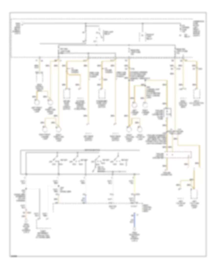
Power Distribution Wiring Diagram (3 of 4) for Chevrolet Colorado 2012
List of elements for Power Distribution Wiring Diagram (3 of 4) for Chevrolet Colorado 2012:
- (engine harness, 18 cm front generator pnk
- (fuel injector harness, 4 cm from fuel injector 4 breakout) j104
- (not used)
- 3.7l
- 3.7l & 2.9l
- 5.3l
- A/c relay
- Abs fuse 10a
- Battery control module) j107
- Bck/up fuse 15a
- Engine control module (ecm)
- Erls fuse 15a
- Evaporative emission (evap) canister purge solenoid valve
- Except
- Except 5.3l
- From e trans fuse (diagram 2 of 4)
- From ign g fuse (diagram 3 of 4)
- Front drive axle actuator
- Frt/axl fuse 15a
- Fuel injector
- Fuel injector 1
- Fuel injector 3
- Fuel injector 5
- Fuel injector 7
- Fuel pump flow control module
- Ign fuse 15a
- Ignition coil 1
- Ignition coil 2
- Ignition coil 3
- Ignition coil 4
- Ignition coil 4 (3.7l & 2.9l)
- Ignition coil 5
- Ignition coil 5 (3.7l)
- Ignition coil 6
- Ignition coil 7
- Ignition coil 8
- Inj fuse 15a
- J111
- J112
- J116
- Mass air flow (maf)/ intake air temperature (iat) sensor
- Pcm 1 fuse 10a
- Pnk
- Secondary air injection (air) pump relay (3.7l & 2.9l)
- To inj fuse (diagram 3 of 4)
- Underhood fuse block (left front side of engine compt)
- W/ electric air injection reactor system
- W/ two speed transfer case
- X102 c8
- X125 p
- X2 b2
- X2 c3
- X7 f3
Power Distribution Wiring Diagram (4 of 4) for Chevrolet Colorado 2012
List of elements for Power Distribution Wiring Diagram (4 of 4) for Chevrolet Colorado 2012:
- (chassis harness, 40.5 cm from fuel pump & sender assembly breakout) j400
- 5 volt
- A/c cmprsr fuse 10a
- A/c relay
- A14
- A24
- Acc
- B3 x204
- Backup lamp relay
- Body control module (bcm)
- C11
- Crew cab w/ power window
- Driver door lock/ window switch
- F11
- From f run/ crank relay (diagram 2 of 4)
- From run/crank relay (diagram 2 of 4)
- From splice j208 (diagram 2 of 4)
- Frt prk lamp fuse 10a
- Ignition switch
- Ignition volt
- Input multi-function switch
- J203 (w/ immobilizer) (steering column harness)
- J204 (w/ immobilizer)
- J406 (trailer accessory harness, between left rear tail lamp connector & trailer lighting connector)
- J900 (license lamp harness, 44.5 cm before right license lamp)
- Key in ignition switch
- Left front marker lamp
- Left license lamp
- Left park/turn signal lamp
- Left rear window switch
- Left tail/stop lamp
- Left tail/turn signal lamp
- Off
- Outside rearview mirror switch (if equipped)
- Passenger door lock/ window switch
- Prk/lamp relay
- Rear prk lamp 2 fuse 10a
- Rear prk lamp fuse 15a
- Right front marker lamp
- Right license lamp
- Right park/turn signal lamp
- Right rear window switch
- Right tail/stop lamp
- Right tail/turn signal lamp
- Run
- Start
- Theft deterrent module (tdm) (w/ immobilizer)
- Trailer connector
- Trailer lighting converter
- Trailer lighting converter inline fuse
- Underhood fuse block (left front side of engine compt)
- W/ power window
- W/ trailer tow
- W/o trailer tow
- X1 a48
- X102
- X2 a42
- X200
- X204 b1
- X600