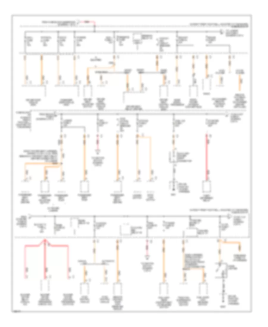
POWER DISTRIBUTION
Power Distribution Wiring Diagram (1 of 4) for Chevrolet Corvette 2003

List of elements for Power Distribution Wiring Diagram (1 of 4) for Chevrolet Corvette 2003:
- (dash harness, 7.5 cm (2.9 in) right of brake switch connectors breakout) s213
- (diagram 1 of 4)
- (engine harness, approx 15 cm (5.9 in) from main harness in branch leading to powertrain control module (pcm)) s120
- (not used)
- (on right rear of engine compartment) fuse block-underhood
- (right side of engine, above starter) g106
- (transmission harness, pnk
- Abs elec fuse 53 20a
- Abs fuse 52 40a
- Air pmp fuse 50 20a
- Air pmp relay
- Air pmp relay 33
- Approx 6.5 cm (2.5 in) from 10 cavity in-line connector, to fuel tank jumper harness)
- Aproach fuse 2 15a
- Automatic transmission (a/t)
- Backup lp relay 38
- Battery
- Cool fan 1 relay
- Cool fan 2 relay 43
- Coolfan fuse 46 30a
- Coolfan1 fuse 49 30a
- Cruise pedal position switch (m/t)
- Drl l relay 40
- Drl r relay
- Electronic brake control module (ebcm)
- Electronic suspension control (esc) module
- Eng ign 1 fuse 19 10a
- Evaporative emission (evap) canister purge solenoid
- Evaporative emission (evap) canister vent solenoid
- F11
- Fog lamp/rear compartment lid release switch
- Fog lp fuse 6 10a
- Fog lp relay 39
- From cool b fan fuse 49 (diagram 1 of 4)
- From cool fan c 2 fuse 46 (diagram 1 of 4)
- From f/pmp fuse 13 n (diagram 4 of 4)
- From ign d relay
- Fuse block- underhood (on right rear of engine compart- ment)
- Fuse block- underhood (on right rear of engine compartment)
- Fuse block-i/p (in right front footwell, mounted to toe board)
- Fusible link (10 ga- rust)
- Fusible link (20 ga- gray)
- Generator
- Hdlpmotlh fuse 4 10a
- Hdlpmotrh fuse 3 10a
- Headlamp door control module
- Horn assembly
- Horn fuse 11 20a
- Horn relay 36
- Ign relay
- Left fog lamp
- Mass air flow (maf) sensor
- Nca
- Pcm b fuse 23 10a
- Pcm fuse 16 10a
- Pnk
- Pnk e
- Powertrain control module (pcm)
- Red
- Reverse inhibit solenoid (m/t)
- Right fog lamp
- Rtd fuse 51 20a
- Rtd fuse 7 10a
- Rtd relay 41
- S400
- Secondary air injection (air) solenoid
- Skip shift solenoid (m/t)
- Starter
- Stoplamp switch
- To aproach fuse 2 (diagram 1 of 4)
- To eng ign 1 fuse 19 (diagram 1 of 4)
- To fuse block-i/p (diagram 2 of 4)
- To ign relay 42 (diagram 1 of 4)
- To throt-cont fuse 17 (diagram 4 of 4)
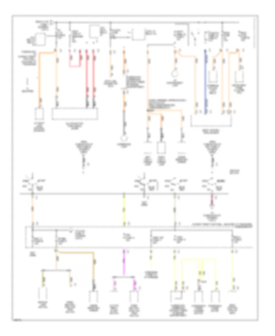
Power Distribution Wiring Diagram (2 of 4) for Chevrolet Corvette 2003
List of elements for Power Distribution Wiring Diagram (2 of 4) for Chevrolet Corvette 2003:
- (dash harness, approximately 22.5 cm (8.8 in) from electronic accessory plug connector) s212
- (in right front footwell, mounted to toe board) fuse block-i/p
- (right power seat harness, approx 4.0 cm (1.5 in), from breakout for right seat relay center connector c1) (w/lumbar) s300
- (w/ power lumbar)
- A12
- Automatic a/c
- Auxiliary power drop connector
- B11
- B12
- Base seat
- Blo mot fuse 30a
- Blower motor control processor (auto a/c)
- Blower motor control processor (manual a/c)
- Blower motor relay (manual a/c)
- Bose fuse 28 20a
- Bose relay 45
- Bose signal processor
- C/ltr fuse 7 20a
- C11
- C12
- Cd changer- remote playback device
- Cigar lighter
- Cnsl cig fuse 1 20a
- Cont- act
- Dcm l fuse 10a
- Dcm r fuse 10a
- Driver door module (ddm)
- Driver seat adjuster switch
- Driver seat control module (scm)
- Driver seat relay center
- E12
- F/tnkdr fuse 32 15a
- F12
- Fog lamp/ rear compartment lid release switch
- From fuse block-underhood a (diagram 1 of 4)
- From g
- From rdo/cd e fuse 5 (diagram 2 of 4)
- Fuel door lock release switch
- Fuse block- i/p (in right front footwell, mounted to toe board)
- G201
- G202
- Hazard switch
- Htchtrk rel relay 39
- Hvac control module
- Hvaccon fuse 27 10a
- If equipped
- Ign1 fuse 47 60a
- Ign2 fuse 50 60a
- Lumbar fuse 3 15a
- Manual a/c
- Nca
- Pasenger ddor module (pdm)
- Passenger seat adjuster switch
- Passenger seat pump
- Passenger seat relay center
- Pwr dl fuse 25a
- Pwr st/ drv circuit breaker 20a
- Pwr st/pas circuit breaker 20a
- Pwrfdr fuse 25a
- Radio
- Radio power antenna (convertible)
- Rdo/ant fuse 24 20a
- Rdo/cd fuse 5 15a
- Red
- Remote control door lock receiver (rcdlr)
- Remote playback device- cd changer (dealer installed)
- Rrdefog fuse 40a
- Rrdefog relay 44
- Scm l fuse 4 10a
- Splice pack 201 (in dash harness)
- Splice pack 202 (in dash harness)
- Sport seat
- Starter fuse 52 (diagram 2 of 4)
- Starter fuse 52 60a
- Stop- lamp switch
- Stp/haz fuse 8 20a
- Theft deterrent relay
- To blo mot fuse 51 (diagram 2 of 4)
- To ignition switch (diagram 3 of 4)
- To lumbar mini fuse 3 (diagram 2 of 4)
- To pk t/lp fuse 6 (diagram 3 of 4)
- Tonn rel fuse 17 10a
- Tonn rel relay 41
- Traction/ suspension control switch
- W/cd player
- W/o cd player
- Wire ends taped to i/p harness
Power Distribution Wiring Diagram (3 of 4) for Chevrolet Corvette 2003
List of elements for Power Distribution Wiring Diagram (3 of 4) for Chevrolet Corvette 2003:
- (dash harness, approximately 22.5 cm (8.8 in) from inside rearview mirror breakout) s200
- (in right front footwell, mounted to toe board) fuse block-i/p
- (not used)
- A/t
- A/t shift lock control solenoid
- A11
- A12
- A14
- Acc
- Alc hdlp relay
- Alc prk lp relay
- Asry off fuse 11 20a
- Backup lamp switch
- Bcm 13 fuse 22 10a
- Bcm a fuse 9 10a
- Bcm1 & ipc fuse 25 10a
- Bcm2 fuse 10a
- Body control module (bcm)
- Btisbu fuse 21 10a
- Bulb test
- C/laldl fuse 10a
- C219
- Clutch pedal start switch
- Crk fuse 14 10a
- Ctsy lp relay 42
- D12
- Data link connector (dlc)
- From c/ltr fuse 7 (diagram 2 of 4)
- From fuse block-i/p ign1 fuse 47 (diagram 2 of 4)
- From fuse block-i/p ign2 fuse 50 (diagram 2 of 4)
- Fuse block- i/p (in right front footwell, mounted to toe board)
- Fuse block- underhood (on right rear of engine compartment)
- Hdlp circuit breaker 20a
- I/p compartment lamp
- If equipped
- Ignition switch
- Inside rearview mirror
- Instrument panel cluster (ipc)
- Left vanity mirror lamp
- M/t
- Monit- ored ld fuse 2 10a
- Monito- red ld relay
- Multifunction turn signal lever
- Nca
- Off
- Park/ neutral position (pnp) switch
- Pk t/lp fuse 6 10a
- Pnk
- Red
- Right vanity mirror lamp
- Start
- Steering column lock relay
- To fuse block-i/p (diagram 4 of 4)
- To hvac fuse 18 (diagram 4 of 4)
- Underhood lamp
- Windshield wiper motor
- Windshield wiper/ washer switch
- Wire ends taped to i/p harness
- Wsw fuse 10 25a
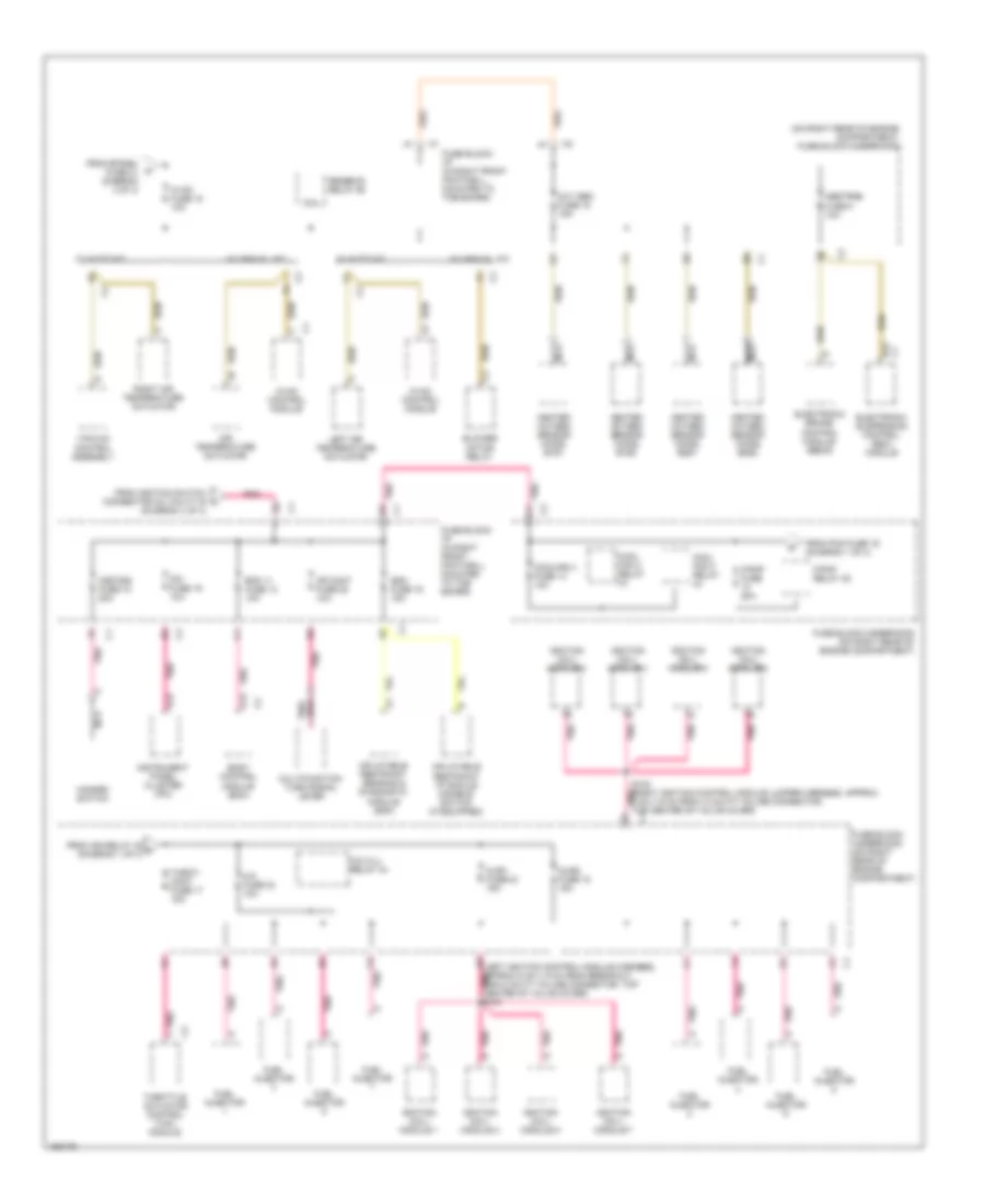
Power Distribution Wiring Diagram (4 of 4) for Chevrolet Corvette 2003
List of elements for Power Distribution Wiring Diagram (4 of 4) for Chevrolet Corvette 2003:
- (on right rear of engine compartment) fuse block-underhood
- A/c clu relay 34
- A/c fuse 24 10a
- A13
- A6 (left ignition control module harness, approx 5 cm (1.9 in) from breakout for 8 cavity in-line connector, top center of valve cover) pnk s103
- Abstrns fuse 5 10a
- Air temperature actuator
- B12
- Bcm 11 fuse 13 10a
- Blower motor relay
- Body control module (bcm)
- Coil
- Cool fan 2 relay
- Cool fan 3 relay
- Coolfan 3 fuse 14 10a
- Cr cont fuse 20 10a
- D13
- Electronic brake control module (ebcm)
- Electronic suspension control (esc) module
- F/pmp fuse 20a
- F/pmp relay 35
- From btsibu fuse 21 (diagram 3 of 4)
- From ign relay 42 m (diagram 1 of 4)
- From ignition switch connector c2, cavity b (diagram 3 of 4)
- From pcm fuse 16 (diagram 1 of 4)
- Fuel injector
- Fuse block- i/p (in right front footwell, mounted to toe board)
- Fuse block- underhood (on right rear of engine compartment)
- Fuse block-underhood (on right rear of engine compartment)
- Hazard switch
- Heated oxygen sensor (ho2s) b1s1
- Heated oxygen sensor (ho2s) b1s2
- Heated oxygen sensor (ho2s) b2s1
- Heated oxygen sensor (ho2s) b2s2
- Hvac control module
- Hvac fuse 18 10a
- Hzdt/sg fuse 15 20a
- Ignition coil/ module 1
- Ignition coil/ module 2
- Ignition coil/ module 3
- Ignition coil/ module 4
- Ignition coil/ module 5
- Ignition coil/ module 6
- Ignition coil/ module 7
- Ignition coil/ module 8
- Inflatable restraint ip module disable switch (if equipped)
- Inflatable restraint sensing & diagnostic module (sdm)
- Injr1 fuse 22 15a
- Injr2 fuse 18 15a
- Instrument panel cluster (ipc)
- Ipc fuse 19 10a
- Left air temperature actuator
- Multifunction turn signal lever
- Nca
- Oxy sen fuse 15 15a
- Pnk
- Pnk a11
- Pnk d5
- Pnk e2
- Right air temperature actuator
- Rrdefog relay 46
- S102 (right ignition control module jumper harness, approx 5 cm (1.9 in) from, 8 cavity in-line connector, top center of valve cover) c1
- Sdm fuse 16 15a
- Throt- cont fuse 17 15a
- Throttle actuator control (tac) module
- Vacuum control assembly
- W/ auto a/c
- W/ manual a/c