POWER DISTRIBUTION
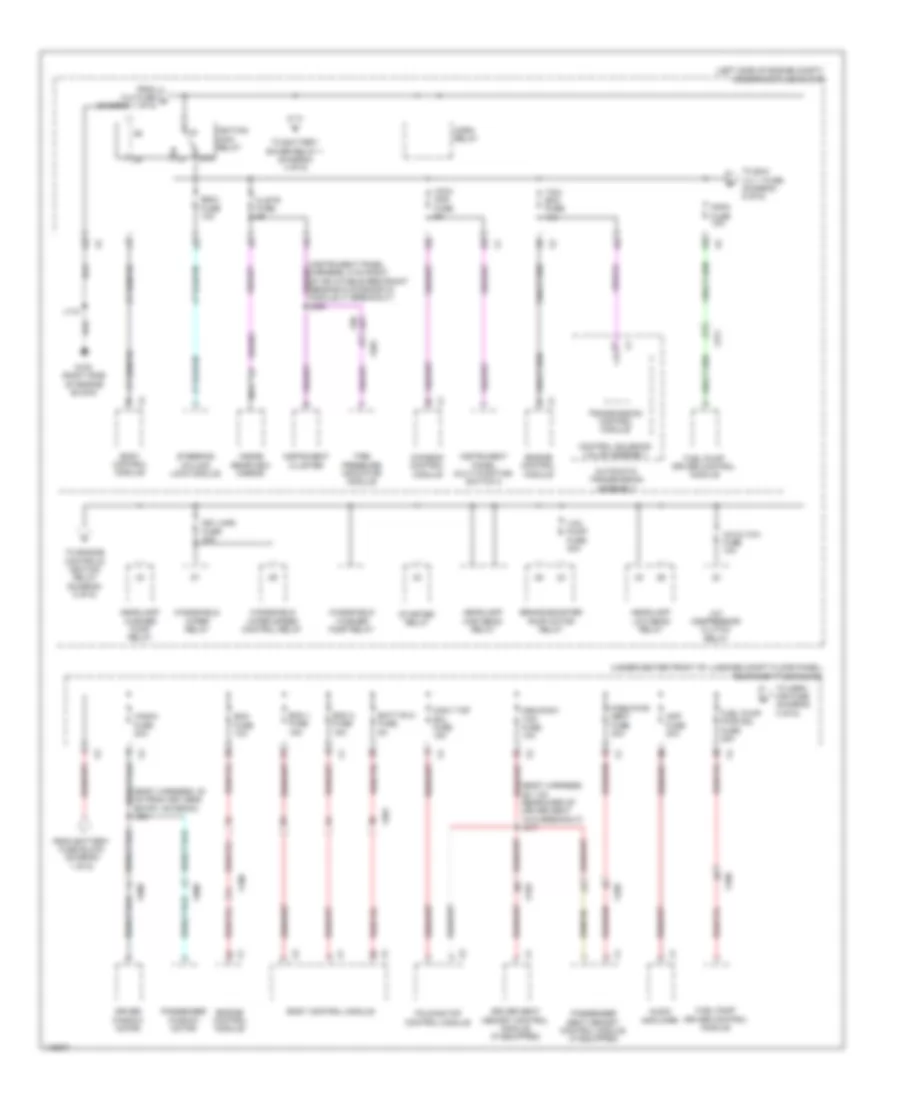
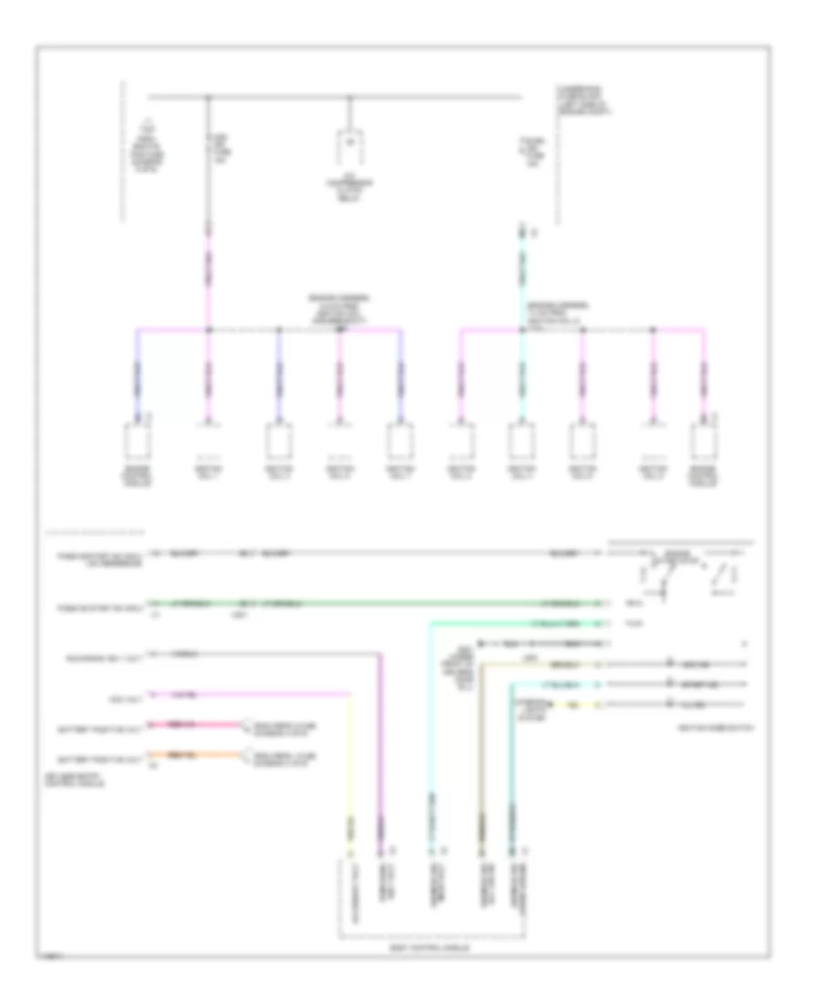
Power Distribution Wiring Diagram (1 of 6) for Chevrolet Corvette Stingray 2014

List of elements for Power Distribution Wiring Diagram (1 of 6) for Chevrolet Corvette Stingray 2014:
- (left side of engine compt) underhood fuse block
- (not used)
- Abs pump fuse 60a
- Abs vlv fuse 30a
- Automatic transmission assembly
- Auxiliary underhood fuse block (near underhood fuse block)
- Battery
- Battery fuse block (on battery positive (+) post)
- Bcm 5 fuse 10a
- Bcm 6 fuse 10a
- Bcm 7 fuse 10a
- Blower motor control module
- Body control module
- Clm fuse 10a
- Cnstr vent fuse 10a
- Control solenoid valve assembly
- Cooling fan control module
- Data link connector
- Dlc fuse 10a
- Elec prk/brk fuse 30a
- Elec rear diff mdl fuse 40a
- Electronic brake control module
- Evaporative emission vent solenoid valve
- Folding top pump motor assembly
- Folding top pump motor relay 1
- Folding top pump motor relay 2
- Frt hvac fuse 40a
- Fuse 100a
- Fuse 225a
- Fuse 350a
- Fuse 60a
- Fuse 80a
- Generator
- Htd/ seat 1 fuse 15a
- Hvac cntrl fuse 15a
- Hvac control module
- J346 (chassis harness, 16 cm from main harness on transmission cooling fan breakout)
- J401 (body harness, 6 cm from fuse block & battery x2, x3 & x4 breakouts)
- J414
- M/t
- Nca
- Park brake control module
- Power steering control module
- Rear differential clutch control module
- Red
- Rev lkout fuse 10a
- Reverse inhibit solenoid actuator
- Rtd fuse 30a
- Seat heating control module
- Starter motor
- Steering column lock module
- Steering column position control module
- Strg col fuse 20a
- Suspension control module (if equipped)
- Tcm fuse 15a
- To ignition main relay (diagram 2 of 6)
- To rear body fuse block (diagram 2 of 6)
- To rear body fuse block (diagram 3 of 6)
- Trans cool fan fuse 20a
- Transmission control module
- Transmission cooling fan module (w/ hd cooling system transmission)
- Used) (not
- X201
- X311
- X312
- X313
- X320
- X403
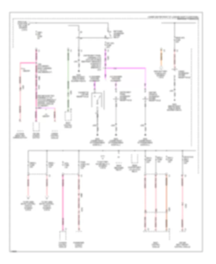
Power Distribution Wiring Diagram (2 of 6) for Chevrolet Corvette Stingray 2014
List of elements for Power Distribution Wiring Diagram (2 of 6) for Chevrolet Corvette Stingray 2014:
- (body harness, 28.1 cm rearward of driver seat x310 breakout) j317
- (body harness, 30 cm from keyless entry antenna) j321
- (left side of engine compt) underhood fuse block
- (under center front of luggage compt floor panel) rear body fuse block
- 87a
- A/c cltch fuse 10a
- A/c compressor clutch relay
- Amp fuse 30a
- Audio amplifier
- Automatic transmission assembly
- Batt rvc fuse 5a
- Bcm 1 fuse 15a
- Bcm 3 fuse 15a
- Body control module
- Brake booster pump motor relay
- Chassis control module
- Clstr fuse 5a
- Control solenoid valve assembly
- Conv top sol fuse 15a
- Driver seat memory control module (if equipped)
- Driver window motor
- Ecm fuse 10a
- Engine control module
- Escl fuse 10a
- Folding top control module
- Fppm fuse 10a
- From battery fuse block (diagram 1 of 6)
- From clm fuse a (diagram 1 of 6)
- Frt wpr fuse 30a
- Fuel pump driver control module
- Fuel pump pwr mdl fuse 25a
- G100 (right side of engine block)
- Headlamp high beam relay
- Headlamp low beam relay
- Headlamp washer pump relay
- Horn relay
- Iccm/ aos fuse 5a
- Ignition main relay
- Inside rearview mirror
- Instrument cluster
- Instrument panel multi-function switch 2
- J118
- Msm/conv top fuse 10a
- Nca
- Pass pwr seat fuse 30a
- Passenger seat memory control module (if equipped)
- Passenger window motor
- Starter relay
- Steering column lock module
- Tcm/ ecm fuse 15a
- Tire pressure indicator module
- To battery saver relay 1 (diagram 4 of 6)
- To engine controls ignition relay (diagram 5 of 6)
- To exh vlv 1 fuse (diagram 5 of 6)
- To osrv mir fuse (diagram 3 of 6)
- Transmission control module
- Vac pump fuse 30a
- Windshield washer pump relay
- Windshield wiper relay
- Windshield wiper speed control relay
- Wndw fuse 30a
- X100
- X201
- X310
- X311
- X320
- X350
- X500
- X600
Power Distribution Wiring Diagram (3 of 6) for Chevrolet Corvette Stingray 2014
List of elements for Power Distribution Wiring Diagram (3 of 6) for Chevrolet Corvette Stingray 2014:
- (body harness, 11 cm into x500 breakout)
- (driver door trim harness, 5.7 cm into main breakout leading to mirror control module) (w/ memory) j503
- (instrument panel harness, 5 cm into inflatable restraint sensing & diagnostic module x1 breakout) j210
- (under center front of luggage compt floor panel) rear body fuse block
- Bcm 2 fuse 15a
- Bcm 4 fuse 15a
- Bcm 8 fuse 30a
- Body control module
- Cargo accessory power receptacle
- Center console accessory power receptacle
- Chassis control module
- Cigarette lighter receptacle
- Driver seat memory control module
- Driver window switch
- Drvr pwr seat fuse 30a
- From battery fuse block (diagram 1 of 6)
- From fuel pump pwr g mdl fuse (diagram 2 of 6)
- Frt apo fuse 20a
- G202 (under front of passenger's door sill)
- G403 (behind right side of rear bumper fascia)
- Iccm fuse 15a
- Instrument panel accessory power receptacle
- J206
- J403
- Mirror control module
- Osrv mir fuse 5a
- Outside rear view mirror switch
- Pass wndw sw fuse 10a
- Passenger window switch
- Peps 1 fuse 10a
- Peps 2 fuse 30a
- Rear apo fuse 30a
- Rear compartment lid unlatch relay
- Rear defogger relay
- Retained accessory power relay
- To battery saver relay 2 (diagram 4 of 6)
- To keyless entry control module (diagram 6 of 6)
- W/ memory
- W/ smokers package accessory
- W/o smokers package accessory
- X201
- X310
- X500
- X515
- X600
- X615
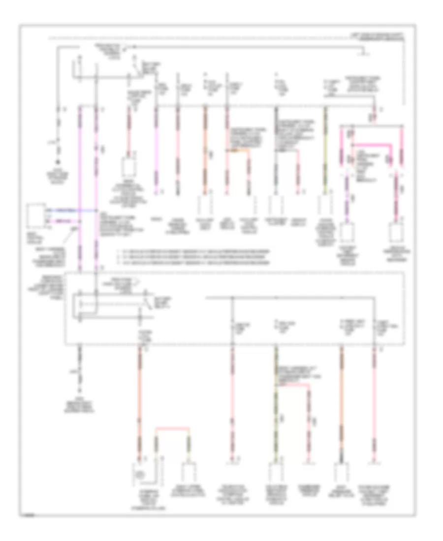
Power Distribution Wiring Diagram (4 of 6) for Chevrolet Corvette Stingray 2014
List of elements for Power Distribution Wiring Diagram (4 of 6) for Chevrolet Corvette Stingray 2014:
- (body harness, 12.2 cm rearward of passenger seat x320 breakout)
- (body harness, 22.7 cm rearward of passenger seat x320 breakout) j311
- (diagram 2 of 6)
- (diagram 3 of 6)
- (instrument panel harness, 12.3 cm right of steering column lock module breakout) (w/headup display) j204
- (instrument panel harness, 5.3 cm into instrument panel courtesy lamp breakout) j223
- (left side of engine compt) underhood fuse block
- Aux outlet fuse 5a
- Auxiliary audio input
- Auxiliary hvac control module
- Battery saver relay 1
- Battery saver relay 2
- Body control module
- Body pressure relief valve
- Content theft deterrent sensor module
- Disply fuse 10a
- Elec rear diff mdl fuse 10a
- From ignition main relay e
- From pass wndw sw fuse j
- G100 (right side of engine block)
- G403 (behind right side of rear bumper fascia)
- Headup display
- Human machine interface control module (w/headup display)
- Inflatable restraint sensing & diagnostic module
- Info display module
- Inside rearview mirror (if equipped)
- Instrument cluster
- Instrument panel compartment door unlatch actuator relay
- Ipc hud fuse 15a
- Isrvm fuse 10a
- J105 (instrument panel harness, 4.1 cm from g105 breakout)
- J118
- J221 (instrument panel harness, 3.3 cm into main bundle downward transition leading to x201)
- J309
- J403
- Nca
- Onstar fuse 10a
- Passenger presence module
- Power sounder content theft deterrent alarm module (if equipped)
- Pres vent (cpe only) fuse 10a
- Radio
- Rdo fuse 15a
- Rear body fuse block (under center front of luggage compt floor panel)
- Rear differential clutch control module (w/ electronic axle positraction limited)
- Right upper steering wheel controls switch
- Sdm aos fuse 10a
- Steering wheel air bag coil (top of steering column)
- Strg whl fuse 2a
- Telematics communication interface control module (w/ onstar)
- Theft dtrnt psm fuse 10a
- Theft/ vim fuse 10a
- Vehicle performance data recorder
- W/ vehicle interior movement sensor & vehicle performance recorder
- W/ vehicle interior movement sensor w/o vehicle performance recorder
- W/o vehicle interior movement sensor w/ vehicle performance recorder
- X201
- X202
- X301
- X302
- X320
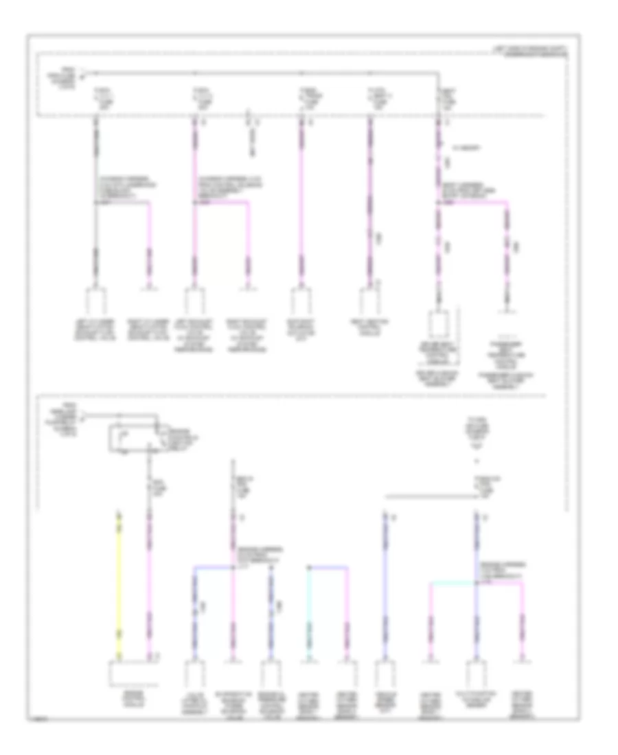
Power Distribution Wiring Diagram (5 of 6) for Chevrolet Corvette Stingray 2014
List of elements for Power Distribution Wiring Diagram (5 of 6) for Chevrolet Corvette Stingray 2014:
- (body harness, 20 cm from keyless entry antenna) j322
- (chassis harness, 5 cm from control solenoid valve assembly breakout) j343
- (chassis harness, 5 cm into underhood fuse block x5 breakout) j341
- (diagram 2 of 6)
- (engine harness, 4 cm from x160 breakout) j115
- (engine harness, 6.8 cm from g107 breakout) j117
- (left side of engine compt) underhood fuse block
- (not used)
- Controls ignition relay
- Driver cushion seat blower assembly
- Driver seat temperature control module
- Ecm fuse 30a
- Eng is pos fuse 15a
- Eng o/s pos fuse 15a
- Eng/ trans fuse 10a
- Engine
- Engine control module
- Engine oil pressure control solenoid valve
- Evaporative emission purge solenoid valve
- Exh vlv 1 fuse 20a
- Exh vlv 2 fuse 20a
- From fppm fuse b
- From headlamp washer c pump relay (diagram 2 of 6)
- Heated oxygen sensor bank 1 sensor 1
- Heated oxygen sensor bank 1 sensor 2
- Heated oxygen sensor bank 2 sensor 1
- Heated oxygen sensor bank 2 sensor 2
- Htd/ seat 2 fuse 15a
- Left cylinder deactivation exhaust flow control valve
- Left exhaust flow control valve (w/ exhaust system performance)
- Multi-function intake air sensor
- Nca
- Passenger cushion seat blower assembly
- Passenger seat temperature control module
- Right cylinder deactivation exhaust flow control valve
- Right exhaust flow control valve (w/ exhaust system performance)
- Seat fan fuse 15a
- Seat heating control module
- Skip shift solenoid actuator (m/t)
- To odd ign fuse (diagram 6 of 6)
- Valve lifter oil manifold assembly
- Vehicle speed sensor (m/t)
- W/ memory
- X106
- X107
- X201
- X310
- X320
Power Distribution Wiring Diagram (6 of 6) for Chevrolet Corvette Stingray 2014
List of elements for Power Distribution Wiring Diagram (6 of 6) for Chevrolet Corvette Stingray 2014:
- (engine harness, 7.4 cm from ignition coil 2) j113
- (engine harness, 8.5 cm from ignition coil one breakout) j108
- A/c compressor clutch relay
- Acc ind
- Acc led sig ign mode sw
- Acc volt
- Accessory volt
- Battery positive volt
- Body control module
- Engine control module
- Engine start/stop
- Even ign fuse 15a
- From eng o/s pos fuse (diagram 5 of 6)
- From peps 1 fuse (diagram 3 of 6)
- From peps 2 fuse (diagram 3 of 6)
- G201 (under front of driver's door sill)
- Ign 1 volt run/crank
- Ignition coil 1
- Ignition coil 2
- Ignition coil 3
- Ignition coil 4
- Ignition coil 5
- Ignition coil 6
- Ignition coil 7
- Ignition coil 8
- Ignition mode switch
- Ill ind
- Interior lights system
- J200
- Keyless entry control module
- Mode volt ign mode sw
- Odd ign fuse 15a
- Passive start sw sig 2
- Passive start sw sig 2 low reference
- Run/crank ign 1 volt
- Start ind
- Start led sig ign mode sw
- Underhood fuse block (left side of engine compt)
- X201