POWER DISTRIBUTION
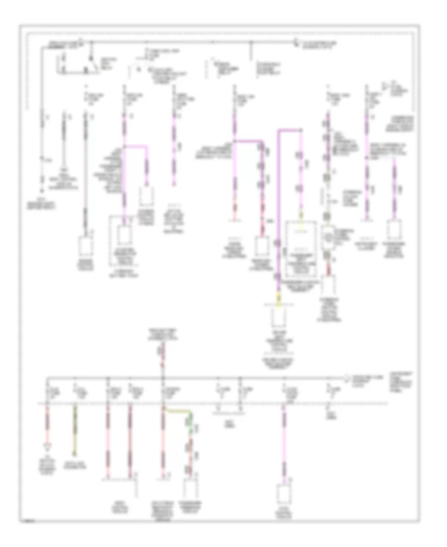
Power Distribution Wiring Diagram (1 of 6) for Chevrolet Impala LS 2014

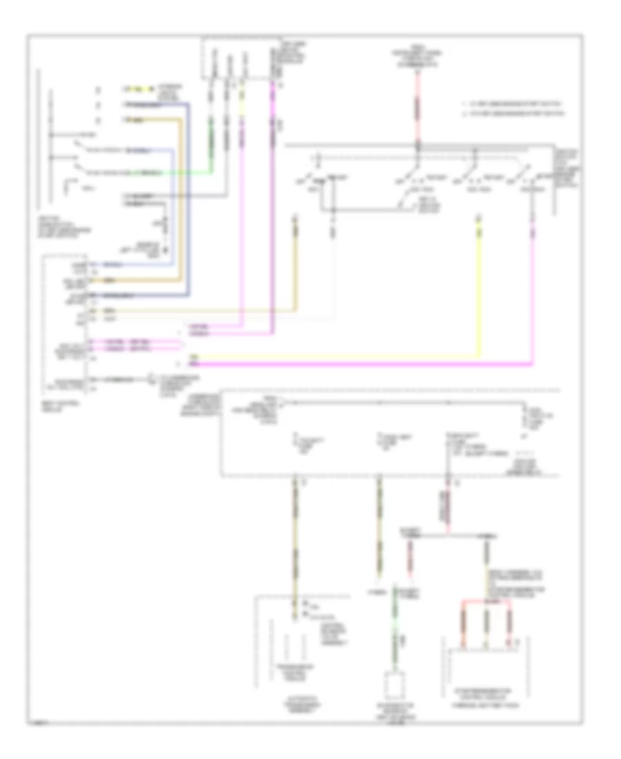
List of elements for Power Distribution Wiring Diagram (1 of 6) for Chevrolet Impala LS 2014:
- (body harness, 5 cm forward of breakout, of branch to x500) (w/ gare door opener) j228
- Abs pump fuse 60a
- Abs valve fuse 30a
- Amp fuse 25a
- Audio amplifier
- Batt rvc fuse 5a
- Battery
- Battery fuse block
- Bcm 6 fuse 15a
- Body control module
- Brake booster pump motor relay (2.4l & 3.6l)
- Brk vac pump fuse 20a
- Ccm fuse 20a
- Chassis control module
- Driver window switch
- Ecm batt fuse 5a
- Electronic brake control module
- Engine control module
- Epb fuse 30a
- Front seat heating control module (if equipped)
- Fuse 100a
- Fuse 250a
- Fuse 300a
- Fuse 30a
- Fuse 60a
- Fuse 80a
- Garage door opener (if equipped)
- Generator
- Htd seat lf fuse 15a
- Htd seat rf fuse 15a
- Keyless entry control module (if equipped)
- Left rear window switch
- Mem seat fuse 5a
- Mir ewl fuse 7.5a
- Mirror control module
- Outside rearview mirror switch
- Parking brake control module
- Passenger window switch
- Peps batt fuse 5a
- Power steering control module (w/ belt drive)
- Power steering control module (w/o belt drive)
- Pwin frt fuse 30a
- Pwin rr fuse 30a
- Rap fuse 30a
- Red
- Right rear window switch
- Seat memory control module
- Starter motor
- Sunroof fuse 30a
- Sunroof motor (if equipped)
- Sunroof sunshade motor module (if equipped)
- To ignition main relay (diagram 2 of 6)
- To instrument panel fuse block (diagram 2 of 6)
- To instrument panel fuse block (diagram 4 of 6)
- Underhood fuse block (right side of engine compt)
- W/ memory
- W/o memory
- X210
- X310
- X320
- X390
- X400
- X500
- X505
- X600
- X605
- X700
- X800
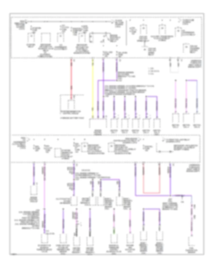
Power Distribution Wiring Diagram (2 of 6) for Chevrolet Impala LS 2014
List of elements for Power Distribution Wiring Diagram (2 of 6) for Chevrolet Impala LS 2014:
- (body harness, 25 cm rearward of breakout to x700) j339
- (not used)
- 7.5a
- Active grille air shutter actuator (if equipped)
- Aero shutter fuse 5a
- Air bag fuse 10a
- Auxiliary heater coolant pump relay (hybrid)
- Bcm 2 fuse 15a
- Bcm 3 fuse 15a
- Body control module
- Body ign fuse 10a
- Body ign2 fuse 15a
- Bpim ign fuse 5a
- C12
- Cabin cool pmp fuse 5a
- Chassis control module (hybrid)
- Data link connector
- Disply ign fuse 5a
- Dlc fuse 7.5a
- Dlis fuse 2a
- Driver cushion seat blower assembly
- Driver seat temperature control module
- Ecm ign fuse 5a
- Engine control module
- From battery fuse block (diagram 1 of 6)
- From body control module (diagram 6 of 6)
- From ccm fuse d (diagram 1 of 6)
- Fuse a
- G101 (engine compt center front)
- Hvac control module
- Hvac/ cntrl fuse 10a
- Hybrid/ev battery pack
- Ignition main relay
- Inflatable restraint sensing & diagnostic module
- Inside rearview mirror (if equipped)
- Instrument cluster
- Instrument panel fuse block (right kick panel)
- J100
- J331 (body harness, 6 cm forward x210 of breakout to x310)
- J336 (body harness, 5 cm rearward of breakout to x700)
- J994
- Passenger air bag disable indicator
- Passenger cushion seat blower assembly
- Passenger presence module
- Passenger seat temperature control module
- Pnk
- Rear defogger relay
- Rearview camera (if equipped)
- Red
- Starter/ generator control module
- Steering column fuse holder
- Steering wheel air bag coil
- Steering wheel heating control module (if equipped)
- To ignition switch (diagram 6 of 6)
- To ip ign (diagram 5 of 6)
- To starter fuse (diagram 3 of 6)
- Trunk rel fuse (diagram 4 of 6)
- Underhood fuse block (right side of engine compt)
- Windshield washer pump relay
- X105
- X210
- X310
- X320
- X400
- X900
- X915
Power Distribution Wiring Diagram (3 of 6) for Chevrolet Impala LS 2014
List of elements for Power Distribution Wiring Diagram (3 of 6) for Chevrolet Impala LS 2014:
- (3.6l: engine harness, 5.9 cm from breakout to x115) (2.4l: engine harness, 6.1 cm from breakout to crankshaft position sensor) (2.4l: engine harness, 16.9 cm from branch to rear of engine components) j106
- (3.6l: engine harness, 9.1 cm from breakout to x160) (2.5l: engine harness, 7 cm from g122) j107
- (engine harness, 35.3 cm from breakout to x160) (3.6l) j133
- 2.4l
- 2.5l
- 2.5l & 3.6l
- 3.6l
- 3.6l & 2.4l
- 3.6l & 2.5l
- A/c clutch fuse 10a
- A/c compressor clutch relay
- Auxiliary transmission fluid pump relay (hybrid)
- Bank 1 sensor 1 heated oxygen sensor (3.6l)
- Bank 1 sensor 2 heated oxygen sensor (3.6l)
- Bank 2 sensor 1 heated oxygen sensor (3.6l)
- Bank 2 sensor 2 heated oxygen sensor (3.6l)
- Bas pwr inverter fuse 175a
- Coil even fuse 15a
- Coil odd fuse 15a
- Cooling fan high speed relay
- Cooling fan low speed relay
- Cooling fan speed control relay
- Ecm fuse 25a
- Engine control module
- Engine controls ignition relay
- Engine oil pressure control solenoid valve (2.5l)
- Evaporative emission purge solenoid valve
- Fan rly a fuse 10a
- From a/c l compressor clutch relay (diagram 3 of 6)
- From e cabin cool pmp fuse (diagram 2 of 6)
- From engine controls ignition relay (diagram 3 of 6)
- Fuel composition sensor
- Heated oxygen sensor 1
- Heated oxygen sensor 2 (2.4l)
- Heated oxygen sensor 2 (2.5l)
- Hybrid/ev battery pack
- Ignition coil 1
- Ignition coil 2
- Ignition coil 3
- Ignition coil 4
- Ignition coil 5 (3.6l)
- Ignition coil 6
- J108 (2.5l: engine harness, 4 cm from branch to camshaft position sensors) (2.4l: engine harness, 4 cm from ignition coil 3) (3.6l: engine harness, 27.3 cm from breakout to x160)
- J227 (3.6l) (body harness, 15.9 cm forward of breakout, of branch to x500)
- Mass air flow/ intake air temperature sensor (2.4l)
- Multi-function intake air sensor
- Nca
- Non walk pt fuse 10a
- Non wlk pt fuse 10a
- Red
- Rocker arm actuator (2.5l)
- Sair pump fuse 50a
- Sair sol fuse 15a
- Secondary air injection pump relay (w/ california emission system)
- Secondary air injection solenoid valve relay (except hybrid)
- Secondary air injection solenoid valve relay (w/ california emission system)
- Secondary air injection solenoid valve relay (w/ california hybrid system)
- Starter fuse 30a
- Starter relay
- Starter/ generator coolant pump relay (hybrid)
- Starter/generator control module
- To ecm fuse (diagram 3 of 6)
- To front fog lamp relay (diagram 5 of 6)
- To sair sol fuse (diagram 3 of 6)
- Underhood fuse block (right side of engine compt)
- X10
- X150
- X190
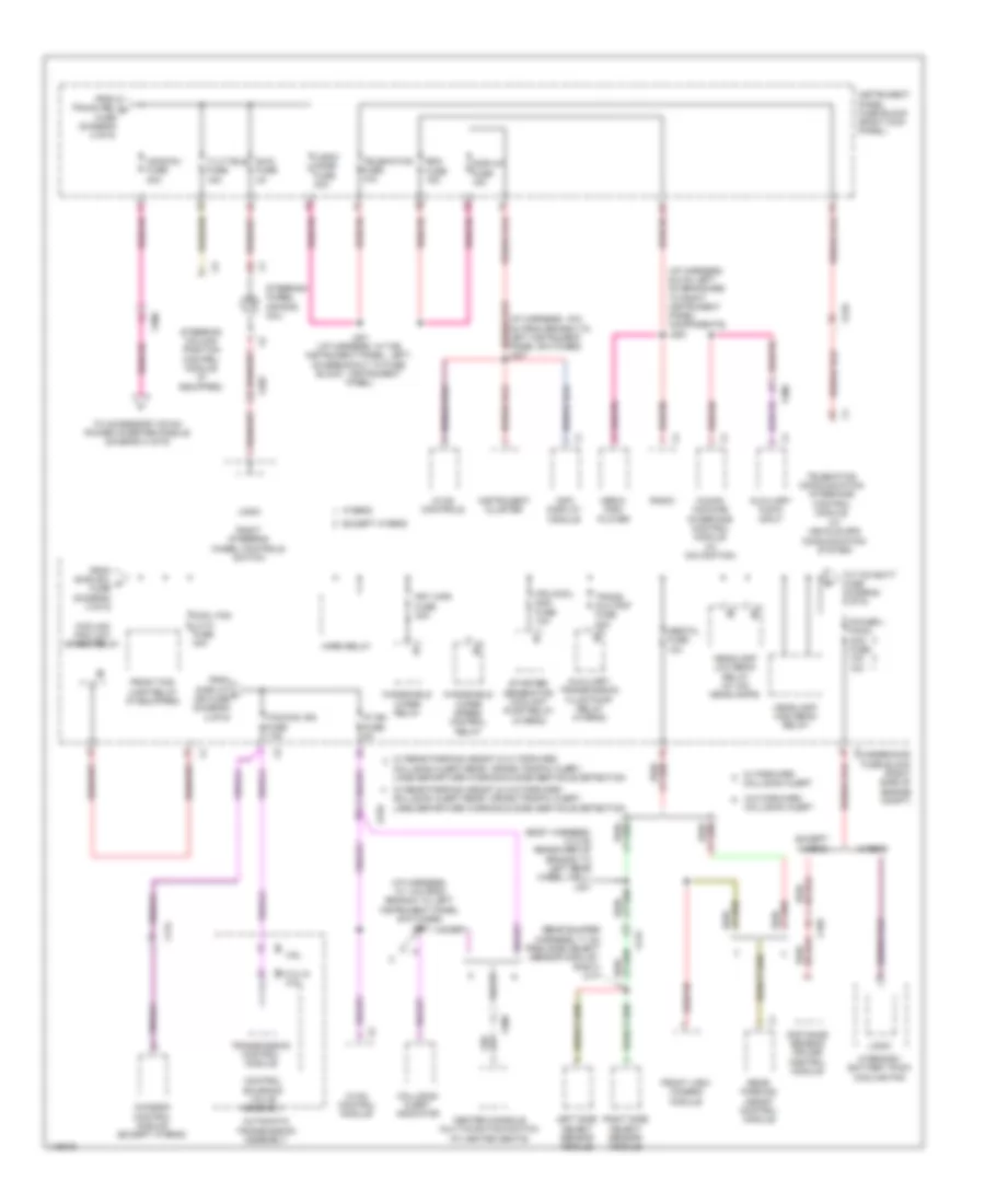
Power Distribution Wiring Diagram (4 of 6) for Chevrolet Impala LS 2014
List of elements for Power Distribution Wiring Diagram (4 of 6) for Chevrolet Impala LS 2014:
- (diagram 2 of 6)
- (or red)
- (w/o ventilated seats: passenger seat x210 cushion harness, in the passenger seat cushion) (w/ ventilated seats: seat temperature x320 control module- passenger, in the passenger seat cushion vent mat) j322
- 110v ac phase a
- 110v ac phase b
- 220v ac phase a
- 220v ac phase b
- Accessory dc/ac power inverter module
- Accessory power receptacle 220v ac (220v ac) accessory power receptacle 110v ac (110v ac)
- Bcm 1 fuse 15a
- Bcm 4 fuse 15a
- Bcm 5 fuse 15a
- Bcm 7 fuse 15a
- Bcm 8 fuse 30a
- Blower motor
- Body control module
- Center console accessory power receptacle
- Center console compartment accessory power receptacle
- Driver seat adjuster switch
- Drvr/seat circuit breaker 25a
- From battery fuse block (diagram 1 of 6)
- From fuse 19 h
- From instrument panel fuse block (diagram 5 of 6)
- From underhood fuse block (diagram 1 of 6)
- Frt/ hvac fuse 40a
- G305 (left front "a" pillar)
- G307 (below driver seat)
- Gnd dc to ac inverter ctrl
- Instrument panel accessory power receptacle
- Instrument panel fuse block (right kick panel)
- J204
- J208
- J301
- Logic
- Nca
- Pass/seat circuit breaker 25a
- Passenger seat adjuster switch
- Passenger seat lumber support switch
- Pwr/ outlet1 fuse 20a
- Pwr/outlet2 fuse 20a
- Rear compartment lid unlatch relay
- Red
- Retained accessory power relay
- Seat memory control module
- To acdcinv (diagram 5 of 6)
- Transmission shift lever position indicator
- Trunk rel fuse 5a
- W/ 2 way power seat
- W/ 8 way power seat
- W/ memory
- W/o memory
- X210
- X300
- X310
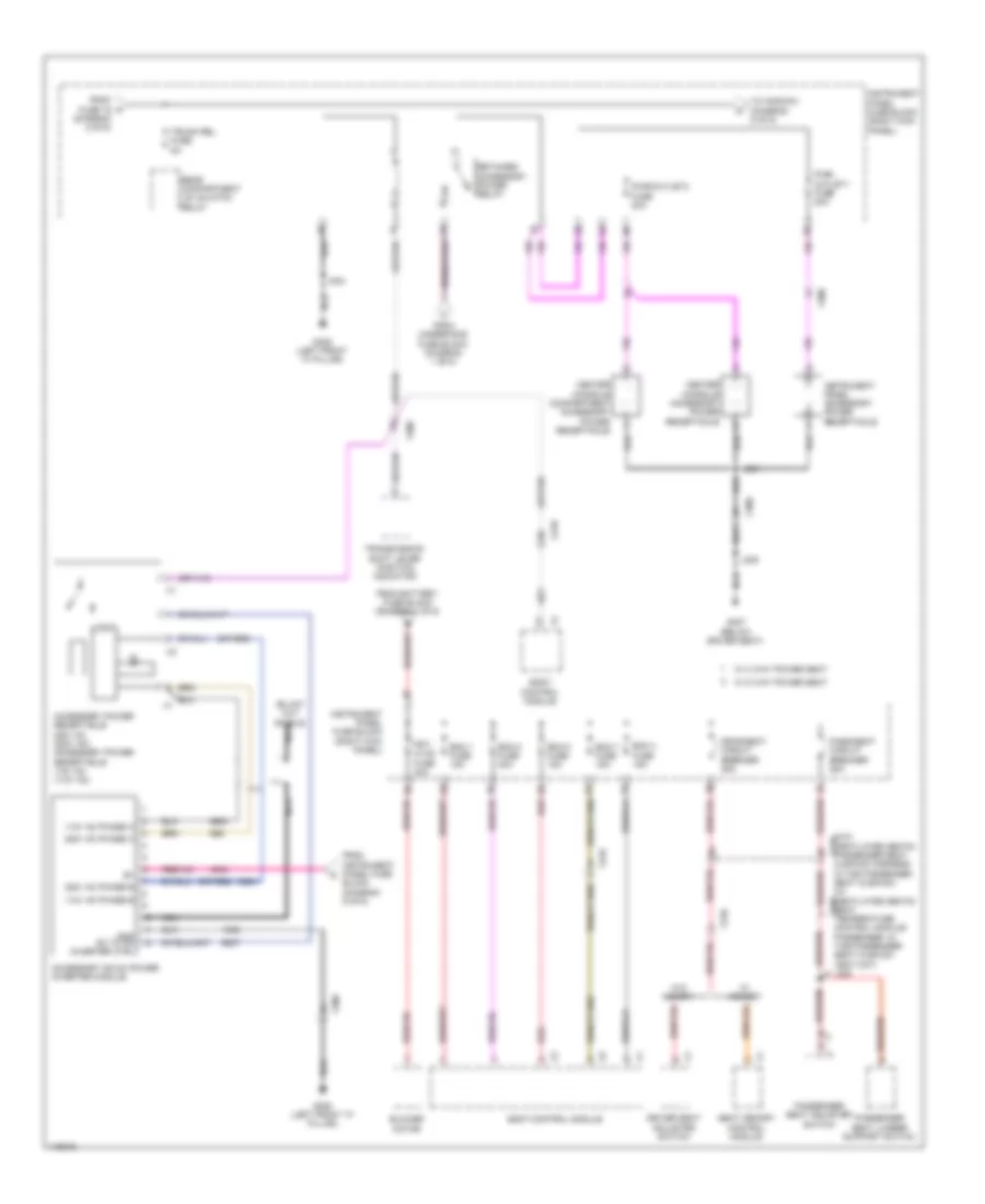
Power Distribution Wiring Diagram (5 of 6) for Chevrolet Impala LS 2014
List of elements for Power Distribution Wiring Diagram (5 of 6) for Chevrolet Impala LS 2014:
- (body harness, 13.2 cm rearward of branch to left rear wheel well) j401
- (i/p harness, 10.1 cm from branch to left instrument panel switches) j210
- (i/p harness, 9.5 cm left of branches to right instrument panel components)
- (rear bumper harness, 71 cm from side object sensor module - right) j417
- (w/ vehicle gps communication system)
- 2.4l & 2.5l
- 3.6l
- Acdcinv fuse 30a
- Automatic transmission assembly
- Auxiliary audio input
- Auxiliary transmission fluid pump relay (hybrid)
- Center console multi-function switch (w/ heated seats)
- Chassis control module (except hybrid)
- Collision alert
- Collision alert indicator
- Collision alert,rear cross traffic alert, lane departure warning & side obstacle detection
- Control solenoid valve assembly
- Cool fan lo k1 fuse 40a
- Cooling fan low speed relay
- Display fuse 15a
- Distance sensing cruise control module
- Except hybrid
- From display f ign fuse (diagram 2 of 6)
- From sair sol m fuse (diagram 3 of 6)
- From trunk rel n fuse (diagram 4 of 6)
- Front fog lamp relay (if equipped)
- Front view camera module
- Frt wpr fuse 30a
- Headlamp high beam relay
- Headlamp low beam relay (w/ hid headlamps)
- Horn relay
- Human machine interface control module (w/ navigation)
- Hvac control module
- Hvac controls
- Hybrid
- Hybrid/ev battery pack cooling fan
- Info display module
- Instrument cluster
- Instrument panel fuse block (right kick panel)
- Ip ign fuse 5a
- J200
- J201 (i/p harness, in the instrument panel, left, on breakout to fuse block - instrument panel)
- Left side object sensor module
- Logic
- Logic/ mode fuse 30a
- Media disc player
- Mgu cool pmp fuse 10a
- Obstcl fuse 10a
- Power pack acc fuse 10a 15a
- Radio
- Rdo fuse 15a
- Rear parking assist control module
- Right side object sensor module
- Right steering wheel controls switch
- Starter/ generator coolant pump relay (hybrid)
- Steering column position control module (if equipped)
- Steering wheel air bag coil
- Swc fuse 2a
- Tcm/ccm ign fuse 7.5a
- Telematics communication interface control module
- Telematics fuse 10a
- Tilt/tele fuse 15a
- To accessory dc/ac power inverter module (diagram 4 of 6)
- To tcm batt fuse (diagram 6 of 6)
- Trans aux pmp fuse 30a
- Transmission control module
- Underhood fuse block (right side of engine compt)
- W/ forward
- W/ rear parking assist & w/ forward
- W/ rear parking assist & w/o forward collision alert,rear cross traffic alert, lane departure warning & side obstacle detection
- W/o forward collision alert
- Windshield wiper relay
- Windshield wiper speed control relay
- X115
- X150
- X202
- X210
- X300
- X415
Power Distribution Wiring Diagram (6 of 6) for Chevrolet Impala LS 2014
List of elements for Power Distribution Wiring Diagram (6 of 6) for Chevrolet Impala LS 2014:
- (base of left "a" pillar) g203
- (body harness, 18.6 cm from breakouts to starter/generator control module) j400
- (except hybrid)
- (hybrid)
- 2.4l & 2.5l
- 3.6l
- Acc
- Acc led
- Acc volt
- Acc volt run/crank ign 1 volt x3
- Automatic transmission assembly
- Body control module
- Bpim batt fuse 7.5a 10a
- Cann vent fuse 5a
- Control solenoid valve assembly
- Cool fan hi k2 fuse 40a
- Cooling fan high speed relay
- Evaporative emission vent solenoid valve
- Except hybrid
- From headlamp p high beam relay (diagram 5 of 6)
- From instrument panel fuse block (diagram 2 of 6)
- Hybrid
- Hybrid/ev battery pack
- Ign
- Ignition mode switch (w/ keyless engine start switch)
- Ignition switch (w/o keyless engine start switch)
- Interior lights system
- Key in ignition switch
- Keyless entry control module
- Led sig
- Low ref
- Mode ctrl
- Mode volt
- Off
- Run
- Run/crank ign 1 volt x2
- Run/crank rly coil ctrl x4
- Start
- Starter/generator control module
- Tcm batt fuse 15a
- To underhood fuse block (diagram 2 of 6)
- Transmission control module
- Underhood fuse block (right side of engine compt)
- W/ keyless engine start switch
- W/o keyless engine start switch
- X210
- X350