POWER DISTRIBUTION
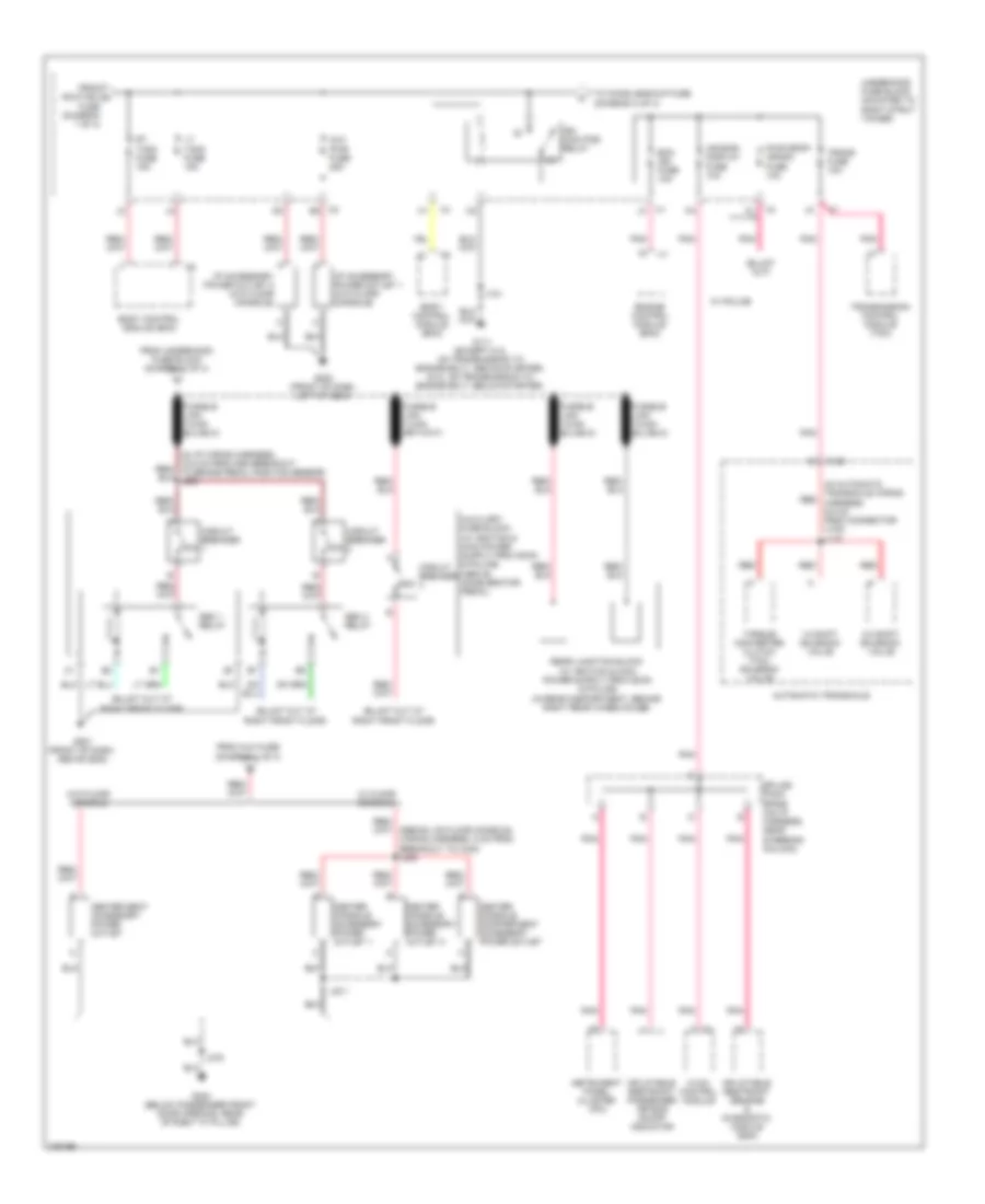
Power Distribution Wiring Diagram (1 of 4) for Chevrolet Impala LT 2008

List of elements for Power Distribution Wiring Diagram (1 of 4) for Chevrolet Impala LT 2008:
- (coupe: in body wiring harness, 7 cm from second breakout to x302) (sedan: in body wiring harness, 10 cm from second breakout to x302) j311
- (in right front kick panel) i/p fuse block
- (mounted to right strut tower) underhood fuse block
- (not used)
- Abs mtr1 fuse 60a
- Abs mtr2 fuse 60a
- Air bag fuse 10a
- Amp fuse 25a
- Audio amplifier (w/ enhanced audio speaker system)
- Automatic transmission shift lock control solenoid
- Aux fuse 20a
- B3 x1
- Batt 1 fuse 60a
- Batt 2 fuse 60a
- Batt 4 fuse 30a
- Battery
- Blower motor control module
- Body control module (bcm)
- Cable pro fuse 200a
- Cnstr fuse 10a
- Digital radio receiver (w/ digital audio)
- Door lock pcb relay
- Door unlock pcb relay
- Dr/lck fuse 25a
- Driver door unlock pcb relay
- Driver seat adjuster switch
- Driver window switch
- Ecm/ tcm fuse 15a
- Electronic brake control module (ebcm) (w/ abs)
- Emergency vehicle headlamp flasher
- Emergency vehicle rear compartment lid lamp relay
- Engine control module (ecm)
- Evaporative emission (evap) canister vent solenoid valve
- From pwr/mir j fuse (diagram 1 of 4)
- G302 (below passenger front door opening, rear of right "a" pillar)
- Generator
- Hdlp mdl fuse 15a
- Heated seat control module
- Htd/ seat fuse 20a
- I/p fuse block (in right front kick panel)
- If equipped
- Inflatable restraint front passenger presence system (pps) module
- Inflatable restraint sensing & diagnostic module (sdm)
- Inside rearview mirror
- Int lts/ pnl dim fuse 15a
- J375
- Outside rearview mirror switch
- Passenger seat adjuster switch
- Passenger window switch
- Pwr/mir fuse 2a
- Pwr/seat circuit breaker 25a
- Pwr/wndw circuit breaker 25a
- Radio
- Radio fuse 20a
- Rap fuse 10a
- Rap relay
- Red
- S/roof fuse 20a
- Starter
- Sunroof motor
- Tan
- To center seat accessory power outlet (diagram 2 0f 4)
- To fusible link (diagram 2 of 4)
- To rt t/sig fuse (diagram 2 of 4)
- To s/roof fuse (diagram 1 of 4)
- Transmission control module (tcm)
- Trunk relay
- W/ 8 way driver seat adjuster
- W/ active brake control
- W/ dual reading lamps & power sliding roof
- W/ dual reading lamps & w/o power sliding roof
- W/ floor shifter
- W/ front heated seats
- W/ headlamp flasher
- W/ police
- W/ power sliding roof & w/o dual reading lamps
- W/o 8 way driver seat adjuster
- W/o active brake control
- W/o headlamp flasher
- X1 c2
- X122
- X3 b1
- X302
- X4 d2
- Xm fuse 10a
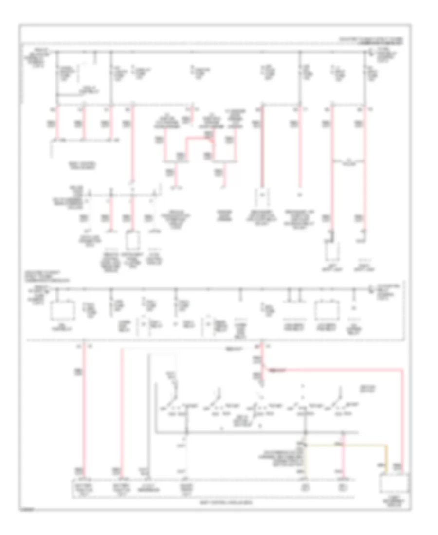
Power Distribution Wiring Diagram (2 of 4) for Chevrolet Impala LT 2008
List of elements for Power Distribution Wiring Diagram (2 of 4) for Chevrolet Impala LT 2008:
- (in automatic transaxle wiring harness, 9.5 cm from connector x100) j115
- 1-2 shift solenoid valve
- 2-3 shift solenoid valve
- 30a
- 50a
- Air bag/ display fuse 10a
- Automatic transaxle
- Aux pwr fuse 25a
- Body control module (bcm)
- Center console accessory power outlet 1
- Center console accessory power outlet 2
- Center console compartment accessory power outlet
- Center seat accessory power outlet
- Circuit breaker
- Ecm ign fuse 10a
- Engine control module (ecm)
- From aux fuse (diagram 1 of 4)
- From hdlp mdl a fuse (diagram 1 of 4)
- From underhood fuse block (diagram 1 of 4)
- G111 (except 5.3l on transmission to engine bolt, above starter) (5.3l: on transmission to engine bolt, below starter)
- G200 (front of dash, left of g204)
- G201 (front of dash, above g202)
- G302 (below passenger front door opening, rear of right "a" pillar)
- Hvac control module
- I/p accessory power outlet 1 (w/o floor console)
- I/p accessory power outlet 2 (w/o floor console)
- Ign main pcb relay
- Inflatable restraint passenger air bag on/off indicator
- Inflatable restraint sensing & diagnostic module (sdm)
- Instrument panel cluster (ipc)
- J101
- J231
- J375
- Lt t/sig fuse 15a
- Pnk
- Pwr drop/ crank fuse 10a
- Red
- Rt t/sig fuse 15a
- Seo 1 relay
- Seo 2 relay
- Splice pack sp206 (on i/p harness, near steering column)
- To chmsl/backup fuse (diagram 3 of 4)
- Torque converter clutch (tcc) solenoid valve
- Trans fuse 10a
- Transmission control module (tcm)
- Underhood fuse block (mounted to right strut tower)
- W/ floor console
- W/ police
- W/o floor console
- X1 j3
- X100
- X2 e2
- X4 k1
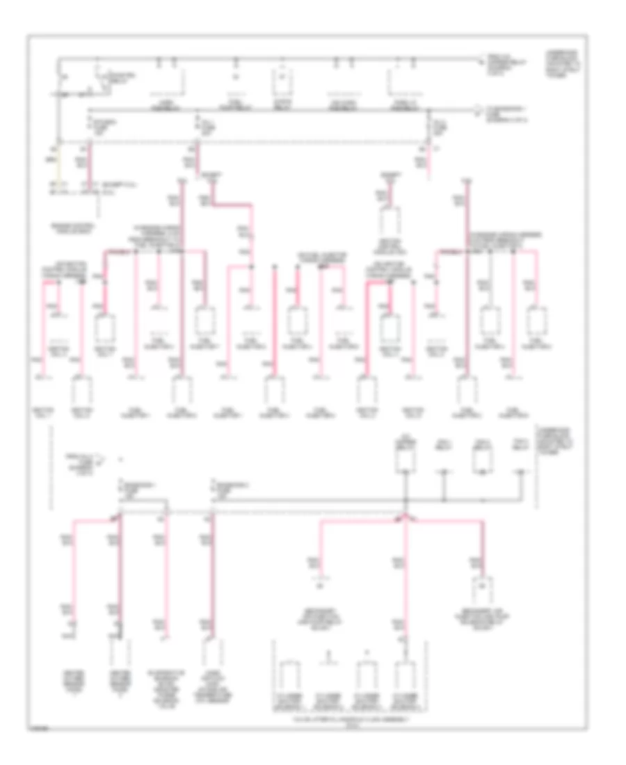
Power Distribution Wiring Diagram (3 of 4) for Chevrolet Impala LT 2008
List of elements for Power Distribution Wiring Diagram (3 of 4) for Chevrolet Impala LT 2008:
- (mounted to right strut tower) underhood fuse block
- 5 volt reference
- A/c cmprsr relay
- Acc
- Acc volt
- Air pump fuse 60a
- Air sol fuse 15a
- Battery positive volt
- Bcm fuse 10a
- Body control module (bcm)
- Chmsl/ backup fuse 10a
- Data link connector (dlc)
- Display fuse 10a
- Drl pcb relay
- Fan 1 fuse 30a
- Fan 1 relay
- Fan 2 fuse 30a
- Fan 3 relay
- Fog lp pcb relay
- From ign main c pcb relay (diagram 2 of 4)
- From rt spot d fuse (diagram 3 of 4)
- Garage door opener
- High beam pcb relay
- Hvac control module
- Ign 1 volt
- Ignition switch
- Instrument panel cluster (ipc)
- Int lights fuse 10a
- J204 (on steering column harness, between bcm connector c1 & ignition switch)
- Key in ignition switch
- Left spot lamp
- Low beam pcb relay
- Lt spot fuse 15a
- Nca
- Off
- On/off/ crank volt
- Onstar fuse 10a
- Pnk
- Rear defog relay
- Remote control door lock receiver (rcdlr)
- Right spot lamp
- Rt spot fuse 15a
- Run
- Rvc sen fuse 10a
- Secondary air injection (air) pump relay (sulev)
- Secondary air injection (air) pump solenoid relay (sulev)
- Splice pack jx206 (on i/p harness, near steering column)
- Start
- Theft deterrent module
- To drl pcb relay (diagram 3 of 4)
- To pwr/trn relay (diagram 4 of 4)
- Vehicle communication interface module (vcim)
- W/ garage door opener w/o onstar
- W/ onstar & garage door opener
- W/ onstar w/o garage door opener
- W/ police
- Wiper high pcb relay
- Wiper pcb relay
- Wpr fuse 25a
- X4 f3
Power Distribution Wiring Diagram (4 of 4) for Chevrolet Impala LT 2008
List of elements for Power Distribution Wiring Diagram (4 of 4) for Chevrolet Impala LT 2008:
- (5.3l)
- (except 5.3l)
- (in engine wiring harness, 5 cm from breakout to fuel injector 3) j108
- (in engine wiring harness, 5 cm from breakout to fuel injector 4) j109
- (on fuel injector wiring harness) j109
- (on ignition control module wiring harness) j106
- (on ignition control module wiring harness) j107
- 5.3l
- A/c cmprsr relay
- Cylinder shutoff solenoid 1
- Cylinder shutoff solenoid 2
- Cylinder shutoff solenoid 3
- Cylinder shutoff solenoid 4
- Emissions 1 fuse 15a
- Emissions 2 fuse 15a
- Engine control module (ecm)
- Etc/ecm fuse 15a
- Evaporative emission (evap) canister purge solenoid valve
- Except 5.3l
- Fan 1 relay
- Fan 2 relay
- Fan 3 relay
- From a/c cmprsr relay (diagram 3 of 4)
- From inj 2 fuse g (diagram 4 of 4)
- Fuel injector 1
- Fuel injector 2
- Fuel injector 3
- Fuel injector 4
- Fuel injector 5
- Fuel injector 6
- Fuel injector 7
- Fuel injector 8
- Fuel/ pump relay
- Heated oxygen sensor (ho2s)
- Horn pcb relay
- Ignition coil 1
- Ignition coil 2
- Ignition coil 3
- Ignition coil 4
- Ignition coil 5
- Ignition coil 6
- Ignition coil 7
- Ignition coil 8
- Ignition control module (icm)
- Inj 1 fuse 20a
- Inj 2 fuse 20a
- Mass air flow (maf)/ intake air temperature (iat) sensor
- Nca
- Park lp pcb relay
- Pnk
- Pwr/trn relay
- Secondary air injection (air) pump relay (sulev)
- Secondary air injection (air) pump solenoid relay (sulev)
- Strtr relay
- To emissions 1 fuse (diagram 4 of 4)
- Underhood fuse block (mounted to right strut tower)
- Valve lifter oil manifold (vlom) assembly (5.3l)
- Ws wash pcb relay