POWER DISTRIBUTION
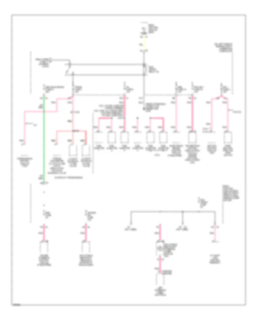
Power Distribution Wiring Diagram (1 of 5) for Chevrolet Malibu Maxx LTZ 2006

List of elements for Power Distribution Wiring Diagram (1 of 5) for Chevrolet Malibu Maxx LTZ 2006:
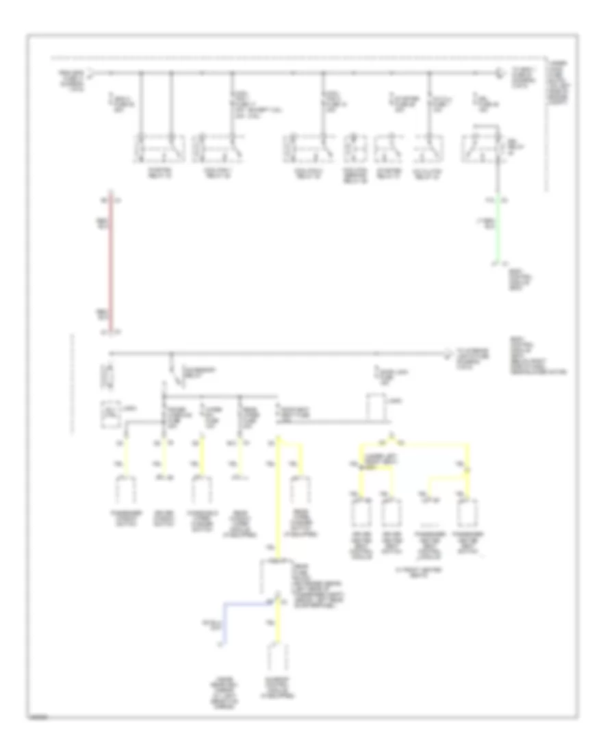
Power Distribution Wiring Diagram (2 of 5) for Chevrolet Malibu Maxx LTZ 2006
List of elements for Power Distribution Wiring Diagram (2 of 5) for Chevrolet Malibu Maxx LTZ 2006:
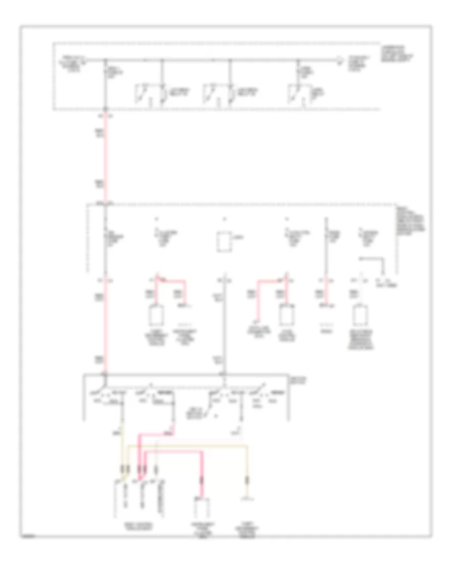
Power Distribution Wiring Diagram (3 of 5) for Chevrolet Malibu Maxx LTZ 2006
List of elements for Power Distribution Wiring Diagram (3 of 5) for Chevrolet Malibu Maxx LTZ 2006:
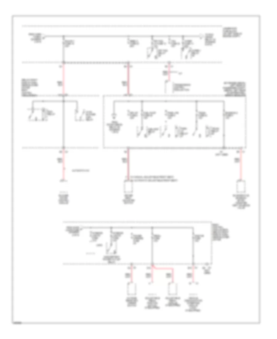
Power Distribution Wiring Diagram (4 of 5) for Chevrolet Malibu Maxx LTZ 2006
List of elements for Power Distribution Wiring Diagram (4 of 5) for Chevrolet Malibu Maxx LTZ 2006:
Power Distribution Wiring Diagram (5 of 5) for Chevrolet Malibu Maxx LTZ 2006
List of elements for Power Distribution Wiring Diagram (5 of 5) for Chevrolet Malibu Maxx LTZ 2006: