POWER DISTRIBUTION
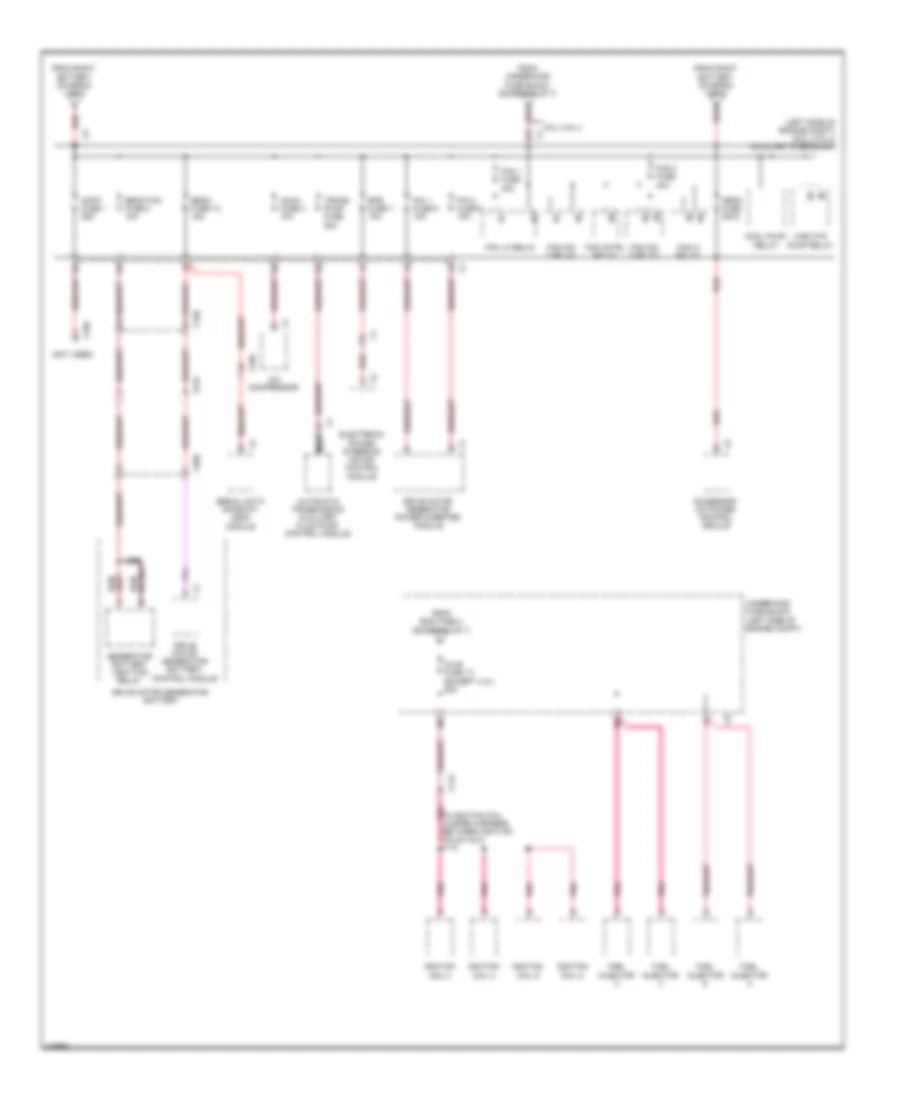
Power Distribution Wiring Diagram (1 of 7) for Chevrolet Silverado 1500 XFE 2013

List of elements for Power Distribution Wiring Diagram (1 of 7) for Chevrolet Silverado 1500 XFE 2013:
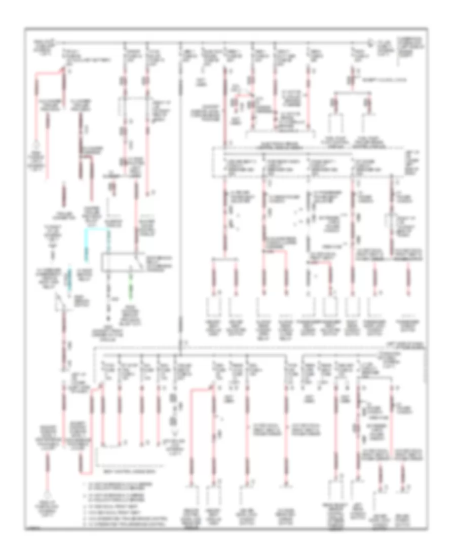
Power Distribution Wiring Diagram (2 of 7) for Chevrolet Silverado 1500 XFE 2013
List of elements for Power Distribution Wiring Diagram (2 of 7) for Chevrolet Silverado 1500 XFE 2013:
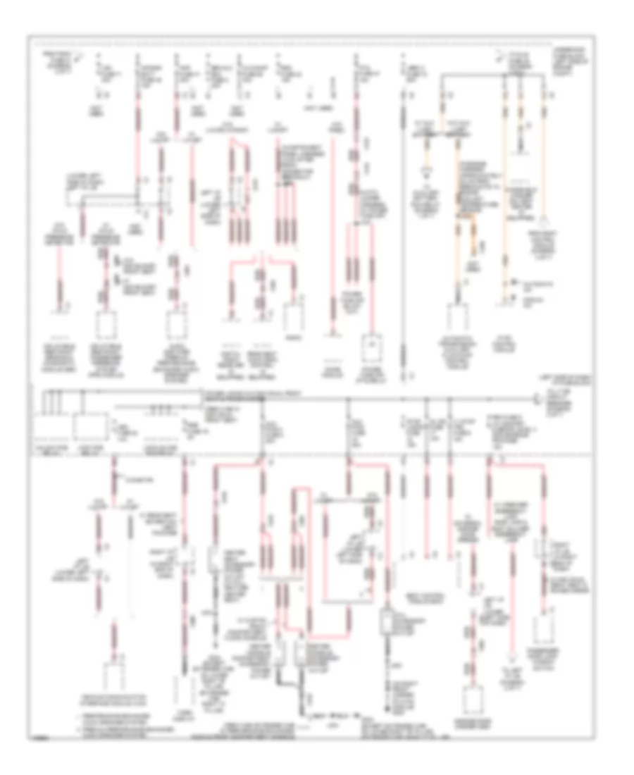
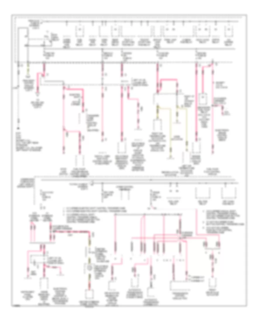
Power Distribution Wiring Diagram (3 of 7) for Chevrolet Silverado 1500 XFE 2013
List of elements for Power Distribution Wiring Diagram (3 of 7) for Chevrolet Silverado 1500 XFE 2013:
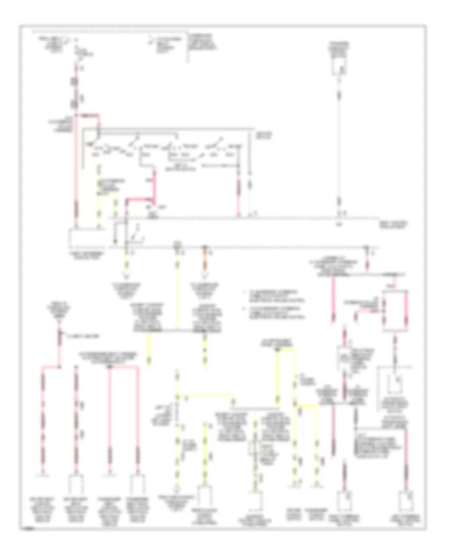
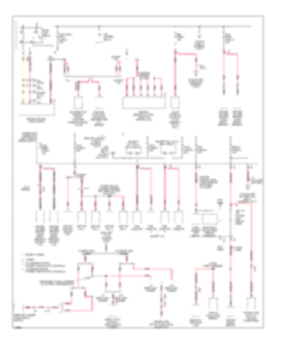
Power Distribution Wiring Diagram (4 of 7) for Chevrolet Silverado 1500 XFE 2013
List of elements for Power Distribution Wiring Diagram (4 of 7) for Chevrolet Silverado 1500 XFE 2013:
Power Distribution Wiring Diagram (5 of 7) for Chevrolet Silverado 1500 XFE 2013
List of elements for Power Distribution Wiring Diagram (5 of 7) for Chevrolet Silverado 1500 XFE 2013:
Power Distribution Wiring Diagram (6 of 7) for Chevrolet Silverado 1500 XFE 2013
List of elements for Power Distribution Wiring Diagram (6 of 7) for Chevrolet Silverado 1500 XFE 2013:
Power Distribution Wiring Diagram (7 of 7) for Chevrolet Silverado 1500 XFE 2013
List of elements for Power Distribution Wiring Diagram (7 of 7) for Chevrolet Silverado 1500 XFE 2013: