POWER DISTRIBUTION
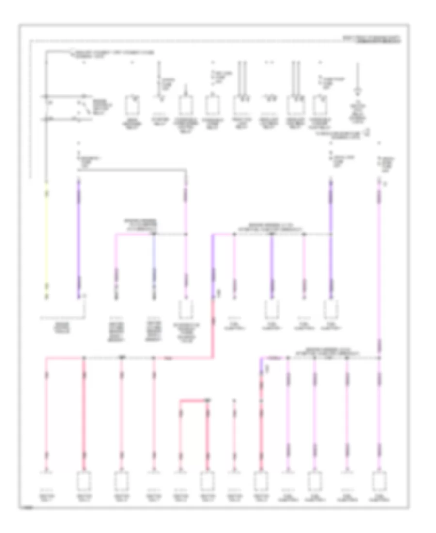
Power Distribution Wiring Diagram (1 of 6) for Chevrolet SS 2014

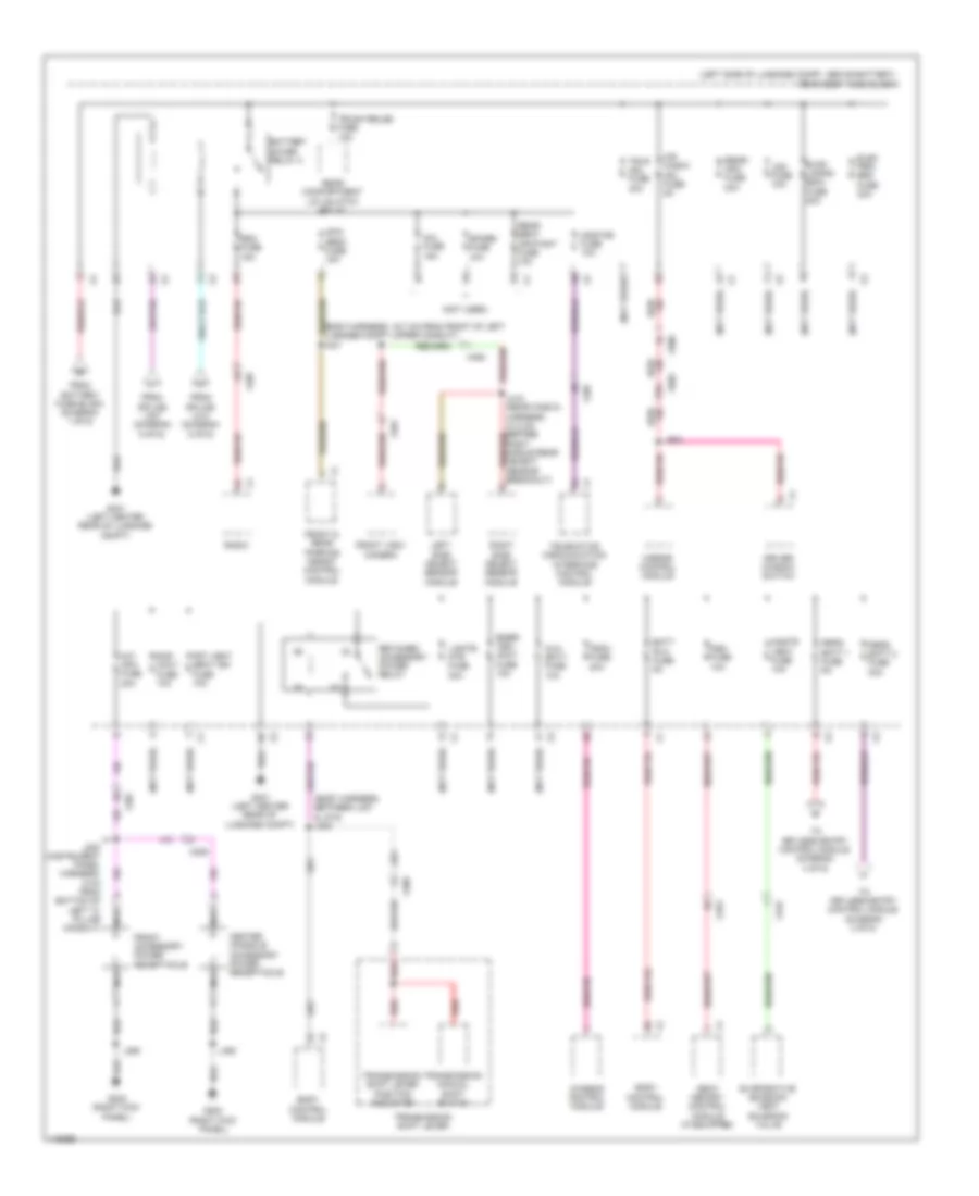
List of elements for Power Distribution Wiring Diagram (1 of 6) for Chevrolet SS 2014:
- (engine harness, 18.5 cm after heated oxygen sensor bank 1 sensor 2 breakout) j122
- (right front of engine compt) underhood fuse block
- 125a
- 225a
- Abs pump fuse 60a
- Abs vlv fuse 30a
- Automatic transmission assembly
- Battery
- Battery fuse block (top of battery
- Control solenoid valve assembly
- Cool fan fuse 60a
- Cooling fan control module
- Drvr pwr seat fuse 30a
- Electronic brake control module
- Frt htd/seat 1/ frt htd/seat 2 fuse 15a
- Fuse 100a
- Fuse 300a
- Fuse 60a
- Generator
- Generator fuse holder (engine compt between generator & battery junction block)
- Instrument panel junction block (lower left side of dash)
- Pass pwr seat fuse 30a
- Pass wndw sw fuse 7.5a
- Passenger seat adjuster switch
- Passenger window switch
- Power steering control module
- Red
- S/roof fuse 20a
- Seat heating control module
- Seat memory control module
- Starter motor
- Sunroof motor
- Tcm/eps fuse 15a
- To engine controls ignition relay (diagram 2 of 6)
- To instrument panel fuse block (diagram 5 of 6)
- To rear body fuse block (diagram 3 of 6)
- To rear body fuse block (diagram 6 of 6)
- Transmission control module
- Underhood provision junction block (right front of engine compt)
- X323
- X324
- X353
- X356
- X357
- X359
- X390
- X402
- X600
- X605
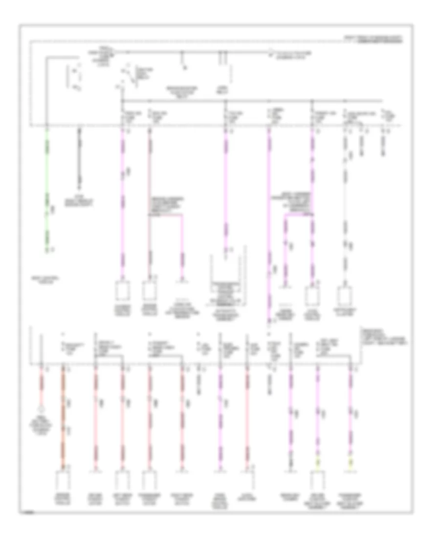
Power Distribution Wiring Diagram (2 of 6) for Chevrolet SS 2014
List of elements for Power Distribution Wiring Diagram (2 of 6) for Chevrolet SS 2014:
- (engine harness, 16.4 cm before g110 breakout) j118
- (engine harness, 5.5 cm after fuel injector 4 breakout) j123
- (engine harness, 5.7 cm after fuel injector 3 breakout) j124
- (right front of engine compt) underhood fuse block
- Ecm/emis 1 fuse 15a
- Engine control module
- Engine controls ignition relay
- Evaporative emission purge solenoid valve
- From frt htd/seat 1/frt htd/seat 2 fuse (diagram 1 of 6)
- Front fog lamp relay
- Frt wpr fuse 30a
- Fuel injector 1
- Fuel injector 2
- Fuel injector 3
- Fuel injector 4
- Fuel injector 5
- Fuel injector 6
- Fuel injector 7
- Fuel injector 8
- Headlamp high beam relay
- Headlamp low beam relay
- Heated oxygen sensor bank 1 sensor 1
- Heated oxygen sensor bank 2 sensor 1
- Ign/inj even fuse 20a
- Ign/inj odd fuse 20a
- Ignition coil 1
- Ignition coil 2
- Ignition coil 3
- Ignition coil 4
- Ignition coil 5
- Ignition coil 6
- Ignition coil 7
- Ignition coil 8
- J144
- J145
- Nca
- Pnk
- Rear defogger relay
- Starter relay
- Strtr fuse 30a
- To emis 2/ign even fuse (diagram 4 of 6)
- To ignition main relay (diagram 3 of 6)
- Wash pump fuse 20a
- Windshield washer pump relay
- Windshield wiper relay
- Windshield wiper speed control relay
- X160
- X161
Power Distribution Wiring Diagram (3 of 6) for Chevrolet SS 2014
List of elements for Power Distribution Wiring Diagram (3 of 6) for Chevrolet SS 2014:
- (body harness crossover section, 10.8 cm left of underbody breakout) j327
- (engine harness, 3.6 cm before throttle body breakout) j116
- (not used)
- (right front of engine compt) underhood fuse block
- Ahl fuse 10a
- Amp fuse 30a
- Aos ign/ipc ign fuse 5a
- Audio amplifier
- Automatic transmission assembly
- Body control module
- Brake booster pump motor relay
- Camera ign fuse 10a
- Chassis control module
- Control solenoid valve assembly
- Driver cushion seat blower assembly
- Driver window motor
- Drvr/lt rear wndw fuse 30a
- Ecm batt fuse 10a
- Ecm ign fuse 15a
- Elec prk/brk fuse 30a
- Engine control module
- From battery fuse block (diagram 1 of 6)
- From wash pump e fuse (diagram 2 of 6)
- Frt vent seat ign fuse 20a
- Fscm ign fuse 10a
- G106 (right rear of engine compt)
- Horn relay
- Hvac control module
- Ignition main relay
- Inside rearview mirror
- Instrument cluster
- Ip/body ign fuse 10a
- Left rear window switch
- Lgm fuse 10a
- Lrbec ign fuse 20a
- Mass air flow/intake air temperature sensor
- Nca
- Park brake control module
- Pass/rt rear wndw fuse 30a
- Passenger cushion seat blower assembly
- Passenger window motor
- Rear body fuse block (left side of luggage compt, above battery)
- Rearview camera
- Right rear window switch
- Tcm ign fuse 15a
- To a/c cltch fuse (diagram 4 of 6)
- Transmission control module
- Trlr mdl ign fuse 10a
- X115
- X209
- X323
- X324
- X345
- X350
- X353
- X356
- X359
- X391
- X460
- X500
- X600
- X700
- X801
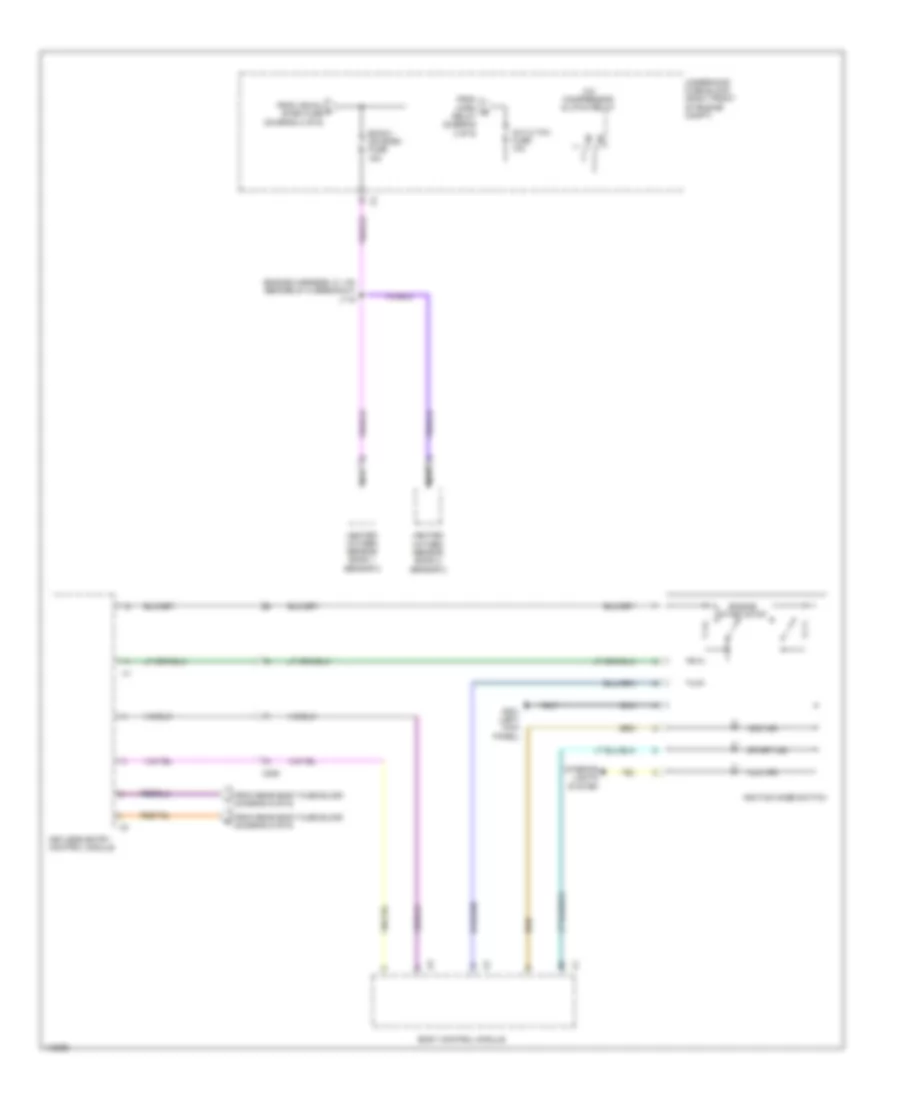
Power Distribution Wiring Diagram (4 of 6) for Chevrolet SS 2014
List of elements for Power Distribution Wiring Diagram (4 of 6) for Chevrolet SS 2014:
- (engine harness, 5.1 cm before g110 breakout j119
- A/c cltch fuse 10a
- A/c compressor clutch relay
- Acc ind
- Body control module
- Emis 2/ ign even fuse 15a
- Engine start/stop
- From horn g relay (diagram 3 of 6)
- From ign/inj f even fuse (diagram 2 of 6)
- From rear body fuse block (diagram 6 of 6)
- G201 (left kick panel)
- Heated oxygen sensor bank 1 sensor 2
- Heated oxygen sensor bank 2 sensor 2
- Ignition mode switch
- Illu ind
- Interior lights system
- Keyless entry control module
- Nca
- Start ind
- Underhood fuse block (right front of engine compt)
- X209
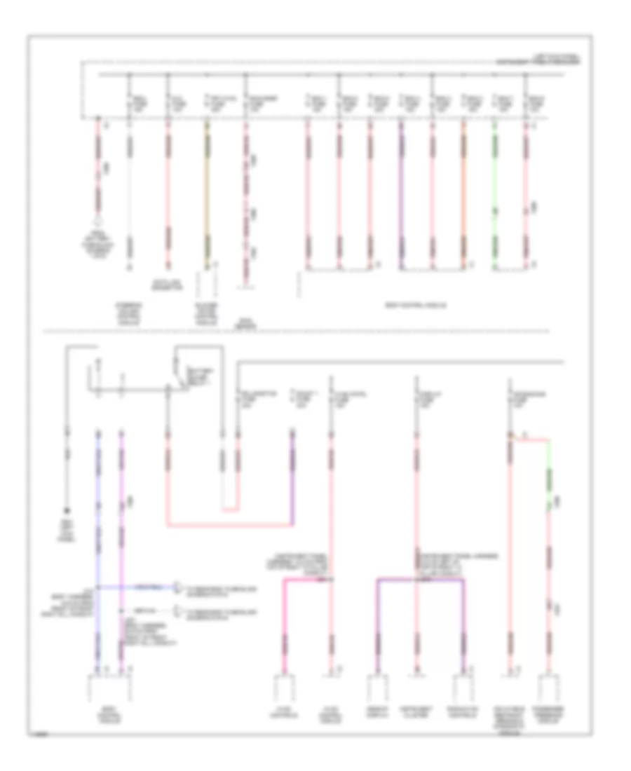
Power Distribution Wiring Diagram (5 of 6) for Chevrolet SS 2014
List of elements for Power Distribution Wiring Diagram (5 of 6) for Chevrolet SS 2014:
- (instrument panel harness, 10.8 cm from top of right "a" pillar conduit) j204
- (left kick panel) instrument panel fuse block
- Air bag/aos fuse 10a
- Battery saver relay 1
- Bcm 1 fuse 15a
- Bcm 2 fuse 15a
- Bcm 3 fuse 15a
- Bcm 4 fuse 15a
- Bcm 5 fuse 15a
- Bcm 6 fuse 10a
- Bcm 7 fuse 15a
- Bcm 8 fuse 30a
- Blower motor control module
- Body control module
- Data link connector
- Display fuse 15a
- Dlc fuse 10a
- Escl fuse 15a
- From battery fuse block (diagram 1 of 6)
- Frt hvac fuse 40a
- G201 (left kick panel)
- Headup display
- Hvac cntrl fuse 15a
- Hvac control module
- Hvac controls
- Inflatable restraint sensing & diagnostic module
- Instrument cluster
- J307 (body harness, 28.9 cm from front of front right sill conduit)
- J310 (body harness, 43.9 cm from front of front right sill conduit)
- Passenger presence module
- R2-logistics fuse 30a
- Radio/hvac controls
- Rain sensor
- Rain snsr fuse 10a
- Shunt 1 fuse 30a
- Steering column control module
- To rear body fuse block (diagram 6 of 6)
- X205
- X209
- X324
- X390
- X392
Power Distribution Wiring Diagram (6 of 6) for Chevrolet SS 2014
List of elements for Power Distribution Wiring Diagram (6 of 6) for Chevrolet SS 2014:
- (body harness, 16.7 cm from front of left luggage compt upper conduit) j401
- (body harness, between j321 & j318) j323
- (left side of luggage compt, above battery) rear body fuse block
- (not used)
- Ahl fuse 15a
- Apa/ sbza fuse 15a
- Aux batt fuse 10a
- Batt rvc fuse 5a
- Battery saver relay 2
- Body control module
- Center console accessory power receptacle
- Chassis control module
- Cnstr vent fuse 10a
- Driver window switch
- Elec prk/ brk fuse 30a
- Emer/ veh/ accy fuse 10a
- Evaporative emission vent solenoid valve
- Evdf lamps/ edim fuse 20a
- From battery fuse block (diagram 1 of 6)
- From splice j307 (diagram 5 of 6)
- From splice j310 (diagram 5 of 6)
- Front & rear parking assist control module
- Front accessory power receptacle
- Front view camera
- Frt vent seat ign fuse 10a
- Fscm fuse 20a
- G202 (right kick panel)
- G401 (left center rear of luggage compt)
- Int/ apo fuse 20a
- J200 (instrument panel harness, 5 cm from bottom of left "a" pillar conduit)
- J250
- J350
- J504
- L/gate mtr fuse 30a
- Left side object sensor module
- Lgm fuse 10a
- Mir wndw mdl fuse 5a
- Mirror control module
- Msm fuse 10a
- Nca
- Onstar fuse 10a
- Peps batt 1 fuse 5a
- Peps batt 2 fuse 30a
- Radio
- Rap accy fuse 10a
- Rdo fuse 15a
- Rear compartment lid unlatch relay
- Rear seat infotmnt fuse 10a
- Rear/ apo fuse 20a
- Red
- Retained accessory power relay
- Right middle rear object sensor breakout)
- Right side object sensor module
- Seat memory control module (if equipped)
- Spare fuse 10a
- Telematics communication interface control module
- To keyless entry control module (diagram 4 of 6)
- Transmission manual shift switch
- Transmission shift lever
- Transmission shift lever position indicator
- Trlr mdl fuse 40a
- Trunk relse fuse 15a
- X206
- X207
- X209
- X315
- X323
- X391
- X460
- X500
- X505