POWER DISTRIBUTION
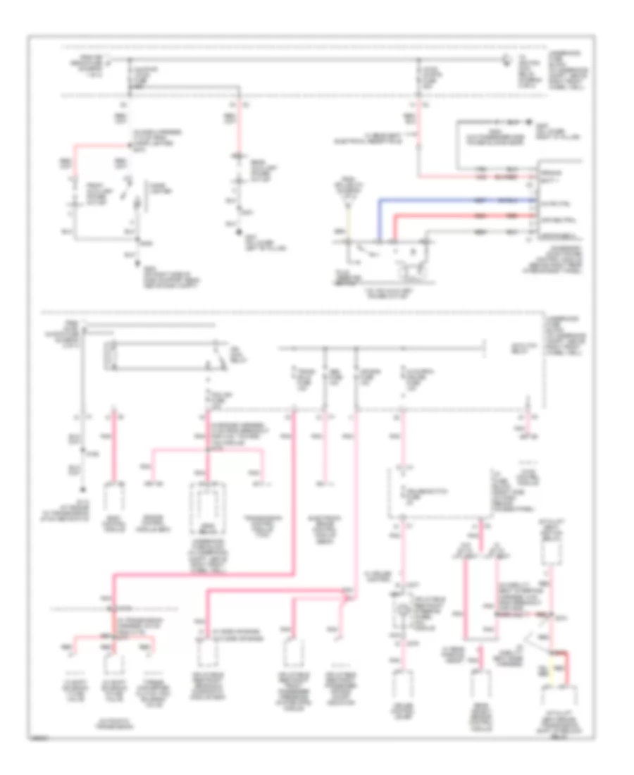
Power Distribution Wiring Diagram (1 of 4) for Chevrolet Uplander LT 2007

List of elements for Power Distribution Wiring Diagram (1 of 4) for Chevrolet Uplander LT 2007:
- (diagram 1 of 4)
- (in engine harness 6.5 cm from breakout for tac module, toward c102) s159
- (in engine harness, 8 cm from breakout for c101, toward ebcm) s139
- 12 volt reference
- A/c cltch fuse 10a
- A/c cltch relay
- Abs motor fuse 60a
- Acc
- Accessory voltage
- Batt main 1 fuse 40a (early production, no information available)
- Batt main 2 fuse 60a
- Batt main 3 fuse 60a
- Batt volt
- Battery
- Blower motor resistor assembly
- Body control module (bcm)
- Crank voltage
- Crnk relay
- Electronic brake control module (ebcm)
- Engine control module (ecm)
- Fan 1 fuse 30a
- Fan 1 relay
- Fan 2 fuse 40a
- Fan 2 relay
- Fan 3 relay
- From batt main 3 fuse b
- From horn fuse c
- Frt blwr hi fuse 40a
- Frt wiper fuse 25a
- Frt wsw fuse 15a
- Fuel pump fuse 15a
- Fuel pump relay
- Fusible link 242 (14 ga- red)
- Generator
- Hi beam relay
- Horn fuse 15a
- Horn relay
- I/p fuse block (right side of dash, behind access panel)
- Ignition switch
- Ignition voltage
- Lo beam relay
- Lock
- Pcm etc fuse 15a
- Pnk
- Pwr/trn relay
- Red
- Rr defog fuse 40a
- Rr defog relay 30
- Run
- Run rly relay
- S135 (in engine harness, 5 cm from breakout for starter motor)
- S160
- S279 (in steering column harness, 20 cm from c201)
- Start
- Starter motor
- Strtr sol fuse 40a
- To 115 vac auxiliary power outlet (diagram 2 of 4)
- To aux/pwr 12vdc fuse (diagram 2 of 4)
- To fan 1 fuse (diagram 1 of 4)
- To frt wsw fuse (diagram 1 of 4)
- To i/p fuse block (diagram 3 of 4)
- To i/p fuse block (diagram 4 of 4)
- Transmission control module (tcm)
- Underhood fuse block (in underhood compt, above right front wheel well)
- W/ rear seat electrical receptacle
- Wpr 1 relay
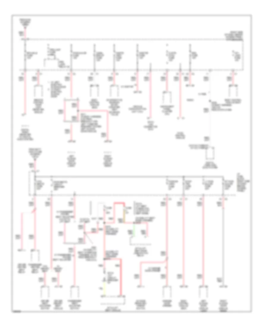
Power Distribution Wiring Diagram (2 of 4) for Chevrolet Uplander LT 2007
List of elements for Power Distribution Wiring Diagram (2 of 4) for Chevrolet Uplander LT 2007:
- (diagram 1 of 4)
- (in dash harness, 17.5 cm from cigar lighter) s270
- (in engine harness, 10 cm from breakout for c102, toward tac module) s175
- (in mobility seat base harness)
- (in mobility seat interface harness, 9 cm from breakout pnk for c206) s362
- (in transmission harness, 9.5 cm from c175) s171
- (w/ side air bags)
- (w/o side air bags)
- 1-2 shift solenoid (1-2 ss) valve
- 115 vac auxiliary power outlet
- 2-3 shift solenoid (2-3 ss) valve
- A10
- Abs fuse 10a
- Ac/cltch relay
- Ac/dc invrtr fuse 25a
- Accessory ac/dc power control module (behind right rear interior body panel)
- Air bag fuse 10a
- Apo neutral
- Apo phase a
- Automatic transmission
- Aux/pwr 12vdc fuse 25a
- Batt +
- Body control module
- C175
- C277
- C279
- Cigar lighter
- Crnk relay
- Cruise control lever
- Cruise/switch fuse 2a
- Electronic brake control module (ebcm)
- Engine control module (ecm)
- From ac/dc e
- From rr defog fuse d
- From splice 273 (diagram 1 of 4)
- Front auxiliary power outlet
- G113 (at engine to transmission stud above g115)
- G200 (on right side of dash support beam, above dash compt)
- G301 (on lower left "b" pillar)
- G400 (on lower right "d" pillar)
- Ground
- Hvac control module
- Hvac/rpa/ cruise fuse 10a
- I/p fuse block (right side of dash, behind access panel)
- Ign main relay
- Inflatable restraint front passenger presence system (pps) module
- Inflatable restraint passenger air bag on/off indicator
- Inflatable restraint sensing & diagnostic module (sdm)
- Inflatable restraint steering wheel coil module
- Invrtr fuse (diagram 2 of 4)
- Invtr ctrl
- Nca
- Pcm ign fuse 10a
- Plug inserted switch
- Pnk
- Rear auxiliary power outlet
- Rear object sensor control module
- Red
- S155
- S246
- S331
- S373
- S374
- S404 (w/o passenger side power sliding door)
- Sit-n-lift seat/ ignition relay
- Sit-n-lift seat/brake transmission shift interlock relay
- To ignition main relay (diagram 2 or 4)
- Torque converter clutch (tcc) solenoid valve
- Trans sols fuse 10a
- Transmission control module (tcm)
- Underhood fuse block (in underhood compt, above right front wheel well)
- W/ cruise control
- W/ rear parking assist
- W/ rear seat electrical receptacle
- W/ sit-n- lift seat
- W/o sit-n- lift seat
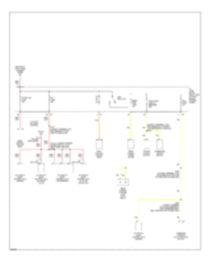
Power Distribution Wiring Diagram (3 of 4) for Chevrolet Uplander LT 2007
List of elements for Power Distribution Wiring Diagram (3 of 4) for Chevrolet Uplander LT 2007:
- (in mobility seat base harness) s372
- (in mobility seat base harness) s376
- (right side of dash, behind access panel) i/p fuse block
- (w/o multimedia) (w/ multimedia)
- Body control module (bcm)
- Chmsl bck/up fuse 15a
- Clstr/ hvac fuse 10a
- Cnstr/ vent fuse 10a
- Data link connector (dlc)
- Digital radio receiver (w/ digital audio system)
- Digital video disc (dvd) player
- Driver heated seat relay
- Driver memory seat module
- Driver seat adjuster switch
- Electric sliding door
- Evaporative emission (evap) canister vent solenoid valve
- From batt main 2 fuse (diagram 1 of 4)
- From s160 (diagram 1 or 4)
- Fuse 25a
- Fuse 3a
- Garage door opener
- Htd/ seats fuse 20a
- Hvac control module
- I/p fuse block (right side of dash, behind access panel)
- Instrument panel cluster (ipc)
- Int/ lamp fuse 10a
- Left sliding door module (lsdm)
- Lt pwr sld dr fuse 40a
- Onstar fuse 10a
- Outside rearview mirror switch
- Passenger heated seat relay
- Passenger seat adjuster switch
- Prk lamp relay 28
- Prk/lamp fuse 10a
- Pwr seats circuit breaker 25a
- Pwr sld dr fuse 15a
- Pwr/mir ugdo fuse 2a
- Radio
- Rdo fuse 15a
- Red
- Remote control door lock receiver (rcdlr)
- Rfa mdls fuse 10a
- Right sliding door module (rsdm)
- Rt pwr sld dr fuse 40a
- S339 (in body harness, 109.2 cm from dvd player)
- S361 (in mobility seat interface harness, 52 cm from breakout for c314)
- S370 (in mobility red
- S411 (in body harness, 6 cm from breakout for left tweeter speaker toward left sliding door module)
- Seat base harness)
- Sit-n- lift circuit breaker 8a
- Sit-n- lift seat fuse block (in sit-n-lift seat base)
- Sit-n-lift seat module
- Sit-n-lift seat/door jamb switch relay
- Stop/ trn fuse 20a
- Vehicle communication unit (vcu)
- W/ garage door opener
- W/ left electric sliding door w/ right
- W/ memory seat
- W/ onstar
- W/ passenger power seat adjuster
- W/ passenger power seat adjuster w/o sit-n- lift seat
- W/ rse
- W/ sit-n- lift seat
- W/o memory seat
Power Distribution Wiring Diagram (4 of 4) for Chevrolet Uplander LT 2007
List of elements for Power Distribution Wiring Diagram (4 of 4) for Chevrolet Uplander LT 2007:
- (in alc jumper harness, inside vehicle, 16 cm from pass-through) s433
- Automatic level control (alc) compressor
- Automatic level control (alc) inflator air switch
- Automatic level control (alc) sensor
- Automatic level control (alc) solenoid valve
- Body control module (bcm)
- Driver window switch
- Elc fuse 20a
- Elc fuse 25a
- From batt main 3 fuse (diagram 1 of 4)
- I/p fuse block (right side of dash, behind access panel)
- Overhead console multi-function switch
- Passenger window switch
- Pwr wndw circuit breaker 25a
- Rap relay 29
- Rear window washer fluid pump relay
- Rear window wiper motor
- Rear/ wpr fuse 15a
- S204 (in dash harness, 10 cm from breakout for c204 toward dash fuse block)
- S300 (in body harness, 20 cm from breakout for passenger seat belt retractor toward c204)
- S415 (in body harness, 5 cm from breakout for c405 toward c479)
- Tan
- Trunk/lks fuse 15a
- W/ auto air level control
- W/ inflator
- W/ trailer provisions