POWER DISTRIBUTION
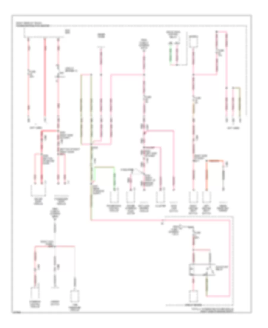
Power Distribution Wiring Diagram (1 of 4) for Dodge Challenger R/T Plus 2011

List of elements for Power Distribution Wiring Diagram (1 of 4) for Dodge Challenger R/T Plus 2011:
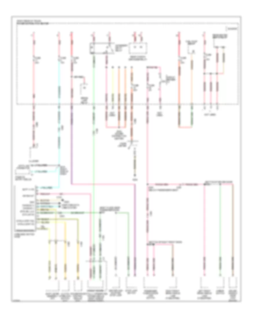
Power Distribution Wiring Diagram (2 of 4) for Dodge Challenger R/T Plus 2011
List of elements for Power Distribution Wiring Diagram (2 of 4) for Dodge Challenger R/T Plus 2011:
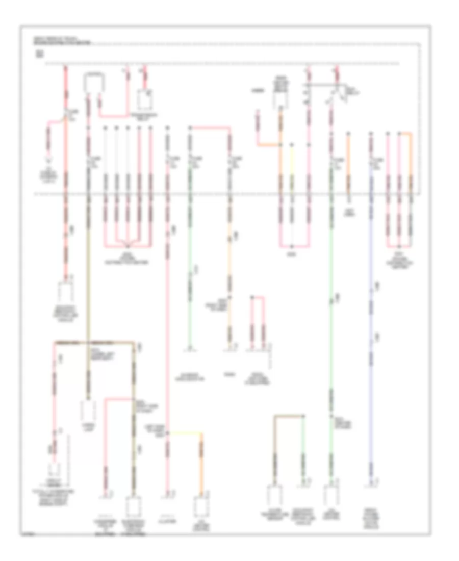
Power Distribution Wiring Diagram (3 of 4) for Dodge Challenger R/T Plus 2011
List of elements for Power Distribution Wiring Diagram (3 of 4) for Dodge Challenger R/T Plus 2011:
Power Distribution Wiring Diagram (4 of 4) for Dodge Challenger R/T Plus 2011
List of elements for Power Distribution Wiring Diagram (4 of 4) for Dodge Challenger R/T Plus 2011: