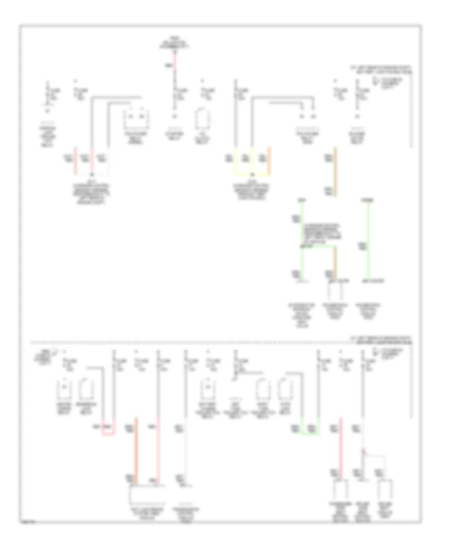
POWER DISTRIBUTION
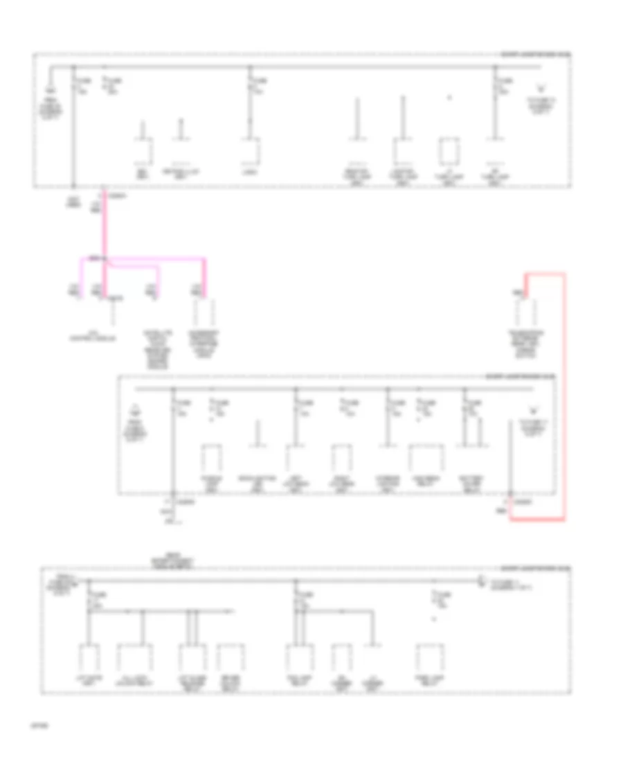
Power Distribution Wiring Diagram (1 of 7) for Ford Cab & Chassis F350 Super Duty 2009

List of elements for Power Distribution Wiring Diagram (1 of 7) for Ford Cab & Chassis F350 Super Duty 2009:
- (diesel: in engine control sensor harness, near right front side of engine) (gas: in engine control sensor harness, near breakout to right front of engine compt) s153
- (in alternator rectifier system harness, in breakout to left front of engine compt) red
- (in alternator rectifier system harness, in breakout to right front of engine compt) (gas) s137
- (in engine control sensor harness, near breakout to right front of engine compt) (diesel) s1014
- (in engine control sensor harness, near breakout to right front of engine compt) s160
- 150a
- Auxiliary heater control module
- Battery
- Battery ii (diesel)
- C197a
- C2463a
- Cable pro
- Diesel
- Diesel w/ dual generators
- Gas
- Generator
- Nca
- Red
- S1015 (diesel) (in engine control sensor harness, near breakout to right front of engine compt)
- S1016 (diesel) (in engine control sensor harness, near breakout to right front of engine compt)
- S1017 (diesel) (in engine control sensor harness, near breakout to right front of engine compt)
- S138 (gas) (in alternator rectifier system harness, in breakout to right front of engine compt)
- S139
- S139 (gas) (in alternator rectifier system harness, in breakout to right front of engine compt)
- S140 (in alternator rectifier system harness, in breakout to left front of engine compt)
- S141 (in alternator rectifier system harness, in breakout to left front of engine compt)
- S143 (in alternator rectifier system harness, in breakout to right front of engine compt)
- S144 (in alternator rectifier system harness, in breakout to right front of engine compt)
- S145 (in alternator rectifier system harness, in breakout to right front of engine compt)
- S152 (diesel: in engine control sensor harness, near right front side of engine) (gas: in engine control sensor harness, near breakout to right front of engine compt)
- S161 (in engine control sensor harness, near breakout to right front of engine compt)
- Secondary generator
- Starter motor
- To fuse 26 (smart junction box (sjb)) (diagram 4 of 7)
- To fuse 40 (battery junction box (bjb)) (diagram 2 of 7)
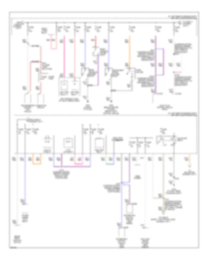
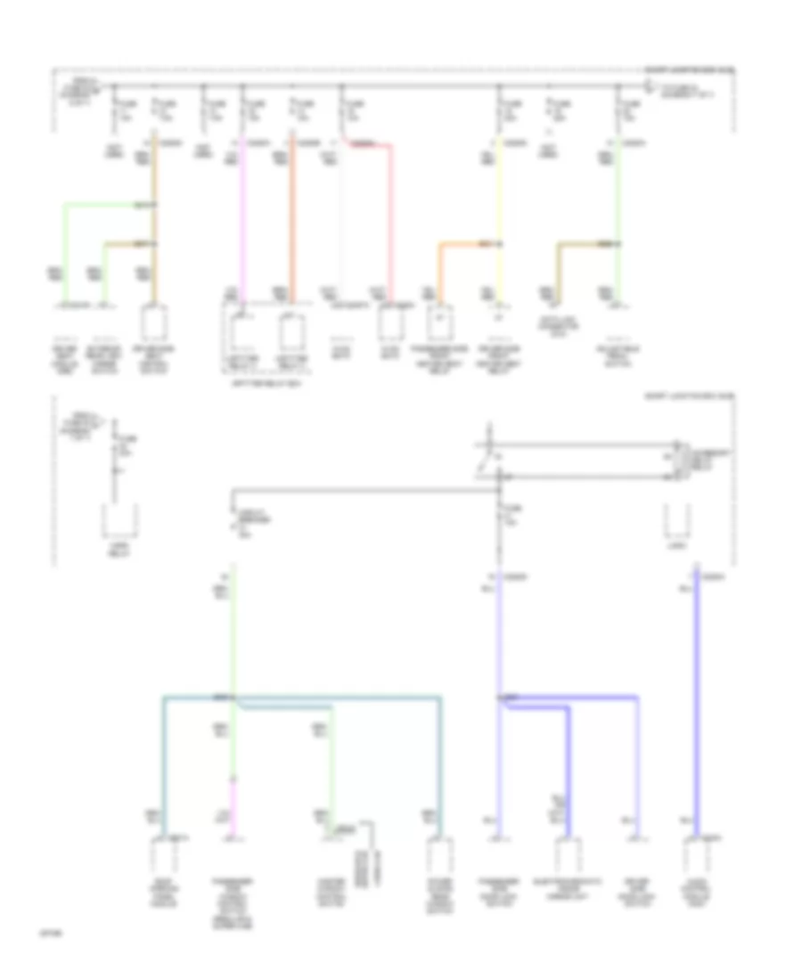
Power Distribution Wiring Diagram (2 of 7) for Ford Cab & Chassis F350 Super Duty 2009
List of elements for Power Distribution Wiring Diagram (2 of 7) for Ford Cab & Chassis F350 Super Duty 2009:
- (at left rear of engine compt) battery junction box (bjb)
- (in engine control sensor harness, near breakout to left front corner of vehicle) s158
- A/c clutch relay
- Anti-lock brake system (abs) module
- Battery charge trailer tow relay
- Blower motor relay
- C1232b
- Diesel
- Driver seat module (dsm)
- Driver side seat control switch
- Evaporative emission (evap) canister vent valve
- From c fuse 24 (diagram 2 of 7)
- From splice s160 (diagram 1 of 7)
- Fuse 10a
- Fuse 15a
- Fuse 20a
- Fuse 25a
- Fuse 30a
- Fuse 40a
- Fuse 50a
- Gas
- Heated mirror relay
- Left turn trailer tow relay
- Parking lamp trailer tow relay
- Passenger side seat control switch
- Pcm power relay (diesel)
- Pcm power relay (gas)
- Powertrain control module (pcm)
- Red
- Reversing lamp relay
- Right turn trailer tow relay
- S117 (in engine control sensor harness, near breakout to left rear of engine compt)
- S154 (in engine control sensor harness, near battery junction box)
- Starter relay
- Stop lamp relay
- To fuse 28 (diagram 2 of 7)
- To fuse 49 (diagram 3 of 7)
- Transmission control module (tcm)
Power Distribution Wiring Diagram (3 of 7) for Ford Cab & Chassis F350 Super Duty 2009
List of elements for Power Distribution Wiring Diagram (3 of 7) for Ford Cab & Chassis F350 Super Duty 2009:
- (at left rear of engine compt) battery junction box (bjb)
- (in engine control sensor harness, near breakout to right rear of engine compt) s103
- Anti-lock brake system (abs) module
- Brake pedal position switch
- C1232b
- C1273a
- C1273b
- C175b
- Cigar lighter
- From d fuse 45 (diagram 2 of 7)
- From fuse 47 (diagram 3 of 7)
- Front console power point
- Front wiper relay
- Fuel pump motor diode
- Fuel pump relay
- Fuse 10a
- Fuse 15a
- Fuse 20a
- Fuse 2a
- Fuse 30a
- Fuse 3a
- Fuse 40a
- Fuse 50a
- Fuse 5a
- G103 (at right rear of engine compt)
- G203 (behind center of dash, behind audio control module)
- G302 (in right "a" pillar)
- Glow plug control module (gpcm)
- Hi to low relay
- Inline fuse
- Instrument panel power point
- Low to hi relay
- Power mirror fold relay
- Powertrain control module (pcm) (diesel)
- Powertrain control module (pcm) (gas)
- Rear console power point
- Red
- Run/start relay
- S1000 (in engine control sensor harness, near breakout to right rear of engine compt)
- S1003 (in engine control sensor harness, near breakout to right rear of engine compt)
- S118 (in engine control sensor harness, near battery junction box)
- S119 (in engine control sensor harness, near breakout to left front corner of vehicle)
- S123 (in engine control sensor harness, near battery junction box)
- S124 (in engine control sensor harness, near breakout to right rear of engine compt)
- S162
- S225
- S272 (w/ ford work solutions)
- S323
- Telematics module
- To fuse 13 (diagram 3 of 7)
- To fuse 33 (smart junction box (sjb)) (diagram 4 of 7)
- To splice s233 (diagram 4 of 7)
- Trailer brake control (tbc) module
- Upfitter relay 1
- Upfitter relay 2
- Upfitter relay box (at right side of dash)
- Video camera
Power Distribution Wiring Diagram (4 of 7) for Ford Cab & Chassis F350 Super Duty 2009
List of elements for Power Distribution Wiring Diagram (4 of 7) for Ford Cab & Chassis F350 Super Duty 2009:
- (not used)
- (w/crew chief) s271
- 4x4 control module
- Acc
- Battery charge trailer tow relay
- Battery junction box (bjb)
- C2280a
- C2280b
- C2280d
- C2280e
- C2280h
- C2357a
- C2463c
- C281b
- Compass sensor module (early production)
- Electric heater
- Electronic shift on the fly (esof) solenoid
- From h fuse 35 (diagram 4 of 7)
- From run/start relay (diagram 3 of 7)
- From splice s119 (diagram 3 of 7)
- From splice s152 (diagram 1 of 7)
- Fuse 10a
- Fuse 20a
- Fuse 5a
- Fuse 7.5a
- Hvac eatc
- Hvac emtc
- Ignition switch
- Instrument cluster (ic)
- Key in switch
- Logic
- Off
- Parking aid module (pam)
- Passenger air bag deactivation (pad) switch
- Passive anti-theft transceiver
- Red
- Restraints control module (rcm)
- Run
- S105
- S206
- S216
- S223
- S227
- S233
- S240
- S314
- Smart junction box (sjb)
- Start
- Tele- matics module (w/crew chief)
- To circuit deactivation ignition module (cdim) (diagram 5 of 7)
- To fuse 36 (diagram 4 of 7)
- To fuse 38 (diagram 5 of 7)
- To fuse 43 (smart junction box (sjb)) (diagram 5 of 7)
- To fuse 44 (smart junction box (sjb)) (diagram 5 of 7)
- To splice s126 (diagram 5 of 7)
- Towl haul switch
- Traction control switch
- Trailer brake control (tbc) module (w/o crew chief)
- Vacuum pump
- W/ cdim
- W/o cdim
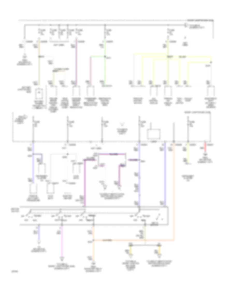
Power Distribution Wiring Diagram (5 of 7) for Ford Cab & Chassis F350 Super Duty 2009
List of elements for Power Distribution Wiring Diagram (5 of 7) for Ford Cab & Chassis F350 Super Duty 2009:
- (diesel)
- (gas)
- (not used)
- 4x4 control module
- Audio amplifier
- Audio control module (acm)
- Batt
- Battery junction box (bjb)
- Battery junction box (bjb) (diesel early production)
- Battery junction box (bjb) (gas & late production diesel)
- Blower motor relay
- C1232b
- C175t
- C2280a
- C2280b
- C2280d
- C2280e
- C2291b
- C240a
- C281b
- Circuit deactivation ignition module (cdim)
- Computer data lines system
- Diesel early production
- Driver side front heated seat relay
- From fuse 27 (diagram 4 of 7)
- From ignition switch (diagram 4 of 7)
- From splice s240 (diagram 4 of 7)
- Front wiper relay
- Fuel tank selector switch
- Fuse 10a
- Fuse 20a
- Fuse 5a
- G300
- Gnd
- Heated mirror relay
- Logic
- Ms can+
- Ms can-
- Otis diode
- Passenger side front heated seat relay
- Powertrain control module (pcm) (gas & late production diesel)
- Run in
- S104
- S126
- S157
- S201
- S224
- S2439
- S265
- S310
- S321
- Smart junction box (sjb)
- Starter relay
- Subwoofer amplifier
- To fuse 2 (diagram 6 of 7)
- Upfitter switch
- W/ cdim
- W/o cdim
- Windshield wiper motor
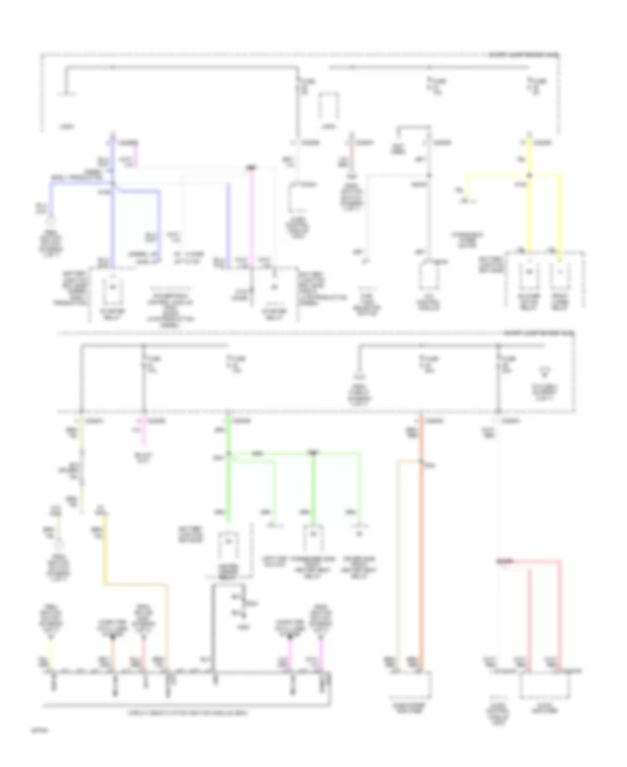
Power Distribution Wiring Diagram (6 of 7) for Ford Cab & Chassis F350 Super Duty 2009
List of elements for Power Distribution Wiring Diagram (6 of 7) for Ford Cab & Chassis F350 Super Duty 2009:
- (not used)
- 4x4 control module
- Accessory protocol interface module (apim)
- All lock/ unlock relay
- Backlighting led (fet)
- Battery saver relay
- Bs1 (fet)
- C2280a
- C2280d
- Driver unlock relay
- Fog lamp relay
- From fuse 25 r (diagram 6 of 7)
- From fuse 39 (diagram 5 of 7)
- From fuse 6 (diagram 6 of 7)
- Fuse 10a
- Fuse 15a
- Fuse 20a
- High beam relay
- Interior lighting (fet)
- Keypad illum (fet)
- Left low beam (fet)
- Lf turn lamp (fet)
- Lh corner (fet)
- Lift gate (fet)
- Lift glass release relay
- Logic
- Lr stop/ turn lamp (fet)
- Nca
- Park lamp relay
- Puddle lamp (fet)
- Rear entertainment module (retm)
- Red
- Rf turn lamp (fet)
- Rh corner (fet)
- Right low beam (fet)
- Rr stop/ turn lamp (fet)
- S204
- Satellite digital audio receiver system (sdars) module
- Smart junction box (sjb)
- Telescoping exterior rear view mirror switch
- To fuse 10 (diagram 6 of 7)
- To fuse 11 (diagram 7 of 7)
- To fuse 17 (diagram 6 of 7)
Power Distribution Wiring Diagram (7 of 7) for Ford Cab & Chassis F350 Super Duty 2009
List of elements for Power Distribution Wiring Diagram (7 of 7) for Ford Cab & Chassis F350 Super Duty 2009:
- (not used)
- Accessory delay relay
- Adjustable pedal switch
- Audio control module (acm)
- C2280a
- C2280b
- C2280d
- C228a
- C2357a
- C240a
- C341b
- C921a
- Circuit breaker 30a
- Crew cab
- Data link connector (dlc)
- Driver seat module (dsm)
- Driver side door lock switch
- Driver side front heated seat relay
- Driver side seat control switch
- Electrochromatic inside mirror unit
- Exterior rear view mirror switch
- From fuse 20 t (diagram 7 of 7)
- From fuse 22 s (diagram 6 of 7)
- Fuse 10a
- Fuse 15a
- Fuse 20a
- Fuse 25a
- Fuse 7.5a
- Horn relay
- Hvac eatc
- Hvac emtc
- Logic
- Master window control switch
- Passenger side door lock switch
- Passenger side front heated seat relay
- Passenger side window control switch (regular & super cab)
- Power sliding rear window switch
- Regular & super cab
- Roof opening panel module
- S228
- S301
- S303
- S311
- S315
- S317
- Smart junction box (sjb)
- To fuse 24 (diagram 7 of 7)
- Upfitter relay 3
- Upfitter relay 4
- Upfitter relay box