POWER DISTRIBUTION
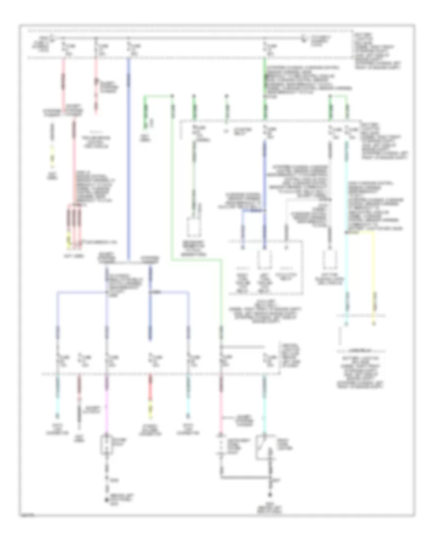
Power Distribution Wiring Diagram (1 of 6) for Ford Econoline E250 2008

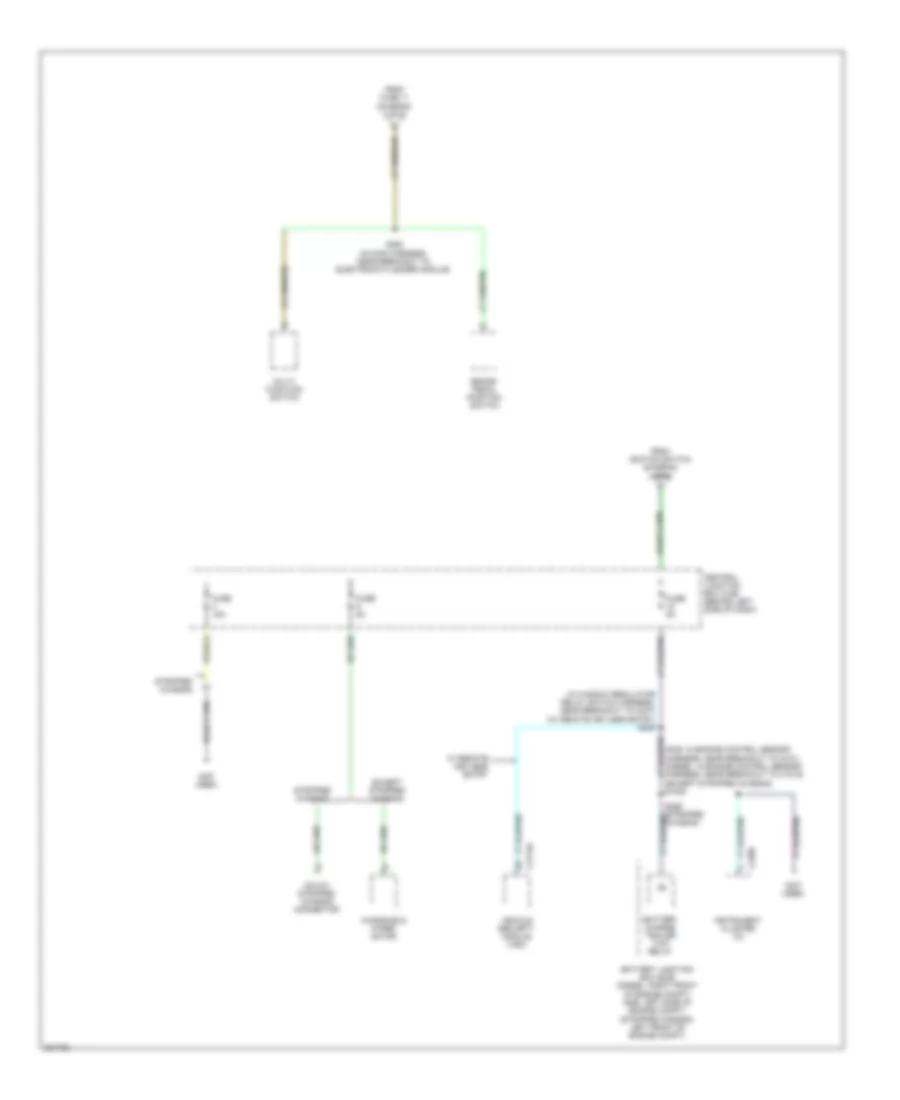
List of elements for Power Distribution Wiring Diagram (1 of 6) for Ford Econoline E250 2008:
- (in alternator rectifier system harness, in breakout to battery) s1073
- (in alternator rectifier system harness, near breakout to battery junction box (bjb)) red s1075
- (in alternator rectifier system harness, near breakout to c146) s191
- (in engine control sensor & fuel charge harness, in breakout to starter motor)
- (in engine control sensor & fuel charge harness, in breakout to starter motor) s1052
- (in engine control sensor & fuel charge harness, in breakout to starter motor) s1072
- (in starter relay & battery ground harness, in breakout to battery) s1074
- (in starter relay & battery ground harness, in breakout to battery) s1076
- (in starter relay to fuse junction panel harness, in breakout to battery) s1007
- (right front of engine compt) battery junction box (bjb)
- Abs test connector
- Battery
- Battery 2
- Battery junction box (bjb) (gas: left side of engine compt) (stripped chassis: left front of engine compt)
- Battery junction box (bjb) (left side of engine compt)
- Battery junction box (bjb) (right front of engine compt)
- Blower motor relay
- C102a (or c1558a)
- C102c (or c1558c)
- C1035a
- C1035b
- C1104a
- C1104c
- C1251b
- C1273a
- C1273b
- C197a
- C197c
- Diesel
- Except diesel
- Fuel injector control module (ficm) power relay
- Fuel pump relay
- Fuse 20a
- Fuse 40a
- Fuse 50a
- Generator
- Glow plug control module (gpcm)
- Red
- Remote jump start terminal
- S1008 (in starter relay to fuse junction panel harness, in breakout to battery)
- S1051 (in engine control sensor & fuel charge harness, in breakout to starter motor)
- S1054 (in engine control sensor & fuel charge harness, in breakout to starter motor)
- S1055 (in engine control sensor & fuel charge harness, in breakout to starter motor)
- S1056 (in engine control sensor & fuel charge harness, in breakout to starter motor)
- S1071
- S1073 (in alternator rectifier system harness, in red breakout to battery junction box (bjb))
- S192 (in alternator rectifier system harness, in breakout to battery)
- Secondary generator
- Starter motor
- To fuse 9 (diagram 2 of 6)
- W/ advance trac
- W/ dual generators
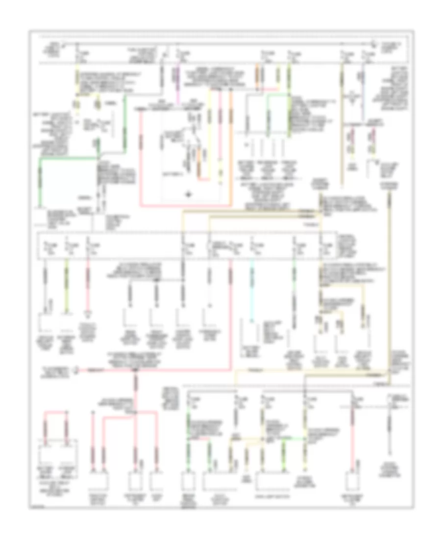
Power Distribution Wiring Diagram (2 of 6) for Ford Econoline E250 2008
List of elements for Power Distribution Wiring Diagram (2 of 6) for Ford Econoline E250 2008:
- (behind left kick panel) g204
- (gas: in engine control sensor harness, in breakout to c219) (diesel: in engine control sensor harness, near breakout to c140) s2012
- (gas: in engine control sensor harness, near breakout to g101) (stripped chassis: in engine control sensor harness, at breakout to abs control module) (diesel: in engine control sensor harness, in breakout to battery junction box (bjb)) s1034
- (in engine control sensor harness, near breakout to auxiliary relay box 1) s1019
- (in window regulator relay switch harness, near breakout to c237) s266
- (not used)
- (stripped chassis: in engine control sensor harness, near breakout to abs control module) (gas: in engine control sensor harness, near breakout to g101) (diesel: in engine control sensor harness, near breakout to c133) s1028
- (stripped chassis: in engine control sensor harness, near breakout to powertrain control module (pcm)) (gas: in engine control sensor harness, in breakout to auxiliary relay box 1) (except diesel) s186
- A/c clutch relay
- Auxiliary relay box 1 (diesel: right front of engine compt) (gas: left rear of engine compt) (stripped chassis: left side of engine compt)
- Battery junction box (bjb) (diesel: right front of engine compt) (gas: left side of engine compt) (stripped chassis: left front of engine compt)
- C1251a
- C219
- Central junction box (cjb) (behind left side of dash)
- Conversion van
- Data link connector
- Daytime running lamps (drl) module
- Except cutaway
- Except stripped chassis
- From a fuse 13 (diagram 1 of 6)
- Front cigar lighter
- Fuse 10a
- Fuse 10a (diesel)
- Fuse 15a
- Fuse 20a
- Fuse 30a
- Fuse 50a
- Fuse 60a
- G203 (behind left end of dash)
- Horn relay
- I/p body builder connector
- Instrument panel power point
- Left turn trailer tow relay
- Power point
- Red
- Right turn trailer tow relay
- S145 (diesel) (in engine control sensor harness, near breakout to g106)
- S207
- S235
- S254
- Secondary generator (w/ dual generators)
- Starter relay
- Stripped chassis
- To fuse 21 (diagram 3 of 6)
- Trailer brake control (tbc) module
Power Distribution Wiring Diagram (3 of 6) for Ford Econoline E250 2008
List of elements for Power Distribution Wiring Diagram (3 of 6) for Ford Econoline E250 2008:
- (diesel)
- (diesel: in breakout to battery junction box (bjb)) (gas: near breakout to g101) (stripped chassis: near breakout to customer access) s1027
- (except diesel)
- (in main harness, in breakout to main light switch) s276
- (in main harness, near breakout to audio unit) s205
- (in main harness, near breakout to c238) s218
- (in main harness, near breakout to c3139) s221
- (in main harness, near breakout to electronic flasher module) s282
- (in main harness, near breakout to g207) s219
- (in window regulator relay switch harness, near breakout to accelerator pedal position sensor) (w/ remote keyless entry) s261
- (in window regulator relay switch harness, near breakout to accelerator pedal position sensor) s291
- (in window regulator relay switch harness, near breakout to brake pedal position (bpp) switch)
- (in window regulator relay switch harness, near breakout to brake pedal position (bpp) switch) s237
- (not used)
- (stripped chassis: at breakout to abs control module) (gas: near breakout to g101) (diesel: in breakout to battery junction box (bjb)) s1033
- 16-way stripped chassis connector
- Audio unit
- Auxiliary battery relay
- Auxiliary blower motor relay
- Auxiliary relay box 2 (behind center of dash)
- Battery 2
- Battery charge trailer tow relay
- Battery junction box (bjb) (diesel: right front of engine compt) (gas: left side of engine compt) (stripped chassis: left front of engine compt)
- Battery saver relay
- Brake pedal position switch
- Breakout to g101) (stripped chassis: near breakout to customer access)
- C1283b
- C1283c
- C1283d
- C1381b
- C175b
- C202a
- C202b
- C2113a
- C220b
- Central junction box (cjb) (behind left side of dash)
- Circuit breaker 30a
- Cutaway
- Diesel
- Driver side front seat control switch
- Evaporative emission (evap) canister vent valve (gas)
- Except cutaway
- Except stripped chassis
- Exterior rear view mirror switch
- From b fuse 18 (diagram 2 of 6)
- Front passenger window/ door lock switch
- Fuel injector control module (ficm) power relay
- Fuse 10a
- Fuse 15a
- Fuse 20a
- Fuse 30a
- Fuse 40a
- Fuse 50a
- Fuse 5a
- Fuse 60a
- Gas w/ auxiliary battery
- Gas w/o auxiliary battery
- I/p body builder connector
- Instrument cluster (ic)
- Interior lamp relay
- Main light switch
- Master window/ door lock/ unlock switch
- Multi- function switch
- Nca
- Parking lamp trailer tow relay
- Pcm power relay
- Powertrain control module (pcm)
- Rear doors door lock switch
- Reversing lamp trailer tow relay
- S1032 (diesel: in breakout to battery junction box (bjb)) (gas: near breakout to g101) (stripped chassis: at breakout to abs control module)
- S225
- Stripped chassis
- To accessory delay relay (diagram 4 of 6)
- To fuse 15 (diagram 4 of 6)
- To multi- function switch (diagram 6 of 6)
- Traction control switch
- Vehicle security module (vsm)
- Vehicle security module (vsm) (w/ rke)
- W/ auxiliary a/c
- Windshield wiper motor
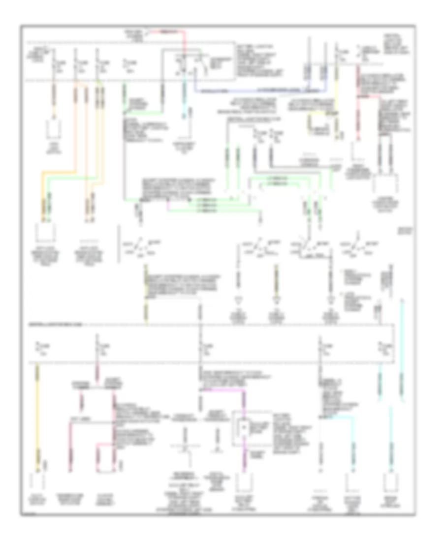
Power Distribution Wiring Diagram (4 of 6) for Ford Econoline E250 2008
List of elements for Power Distribution Wiring Diagram (4 of 6) for Ford Econoline E250 2008:
- (diesel: in breakout to c219) (gas: near breakout for c1033) (stripped chassis: near breakout to c219) s2013
- (except stripped chassis: in window regulator relay switch harness, near breakout to ignition switch) (stripped chassis: in main harness, near breakout to c219) s230
- (except stripped chassis: in window regulator relay switch harness, near breakout to ignition switch) (stripped chassis: in main harness, near breakout to c3139) s280
- (gas: near breakout to c1033) (stripped chassis: near breakout to customer access) (w/ auxiliary battery) s113
- (in left front door window regulator harness, near breakout to exterior rearview mirror switch) s501
- (in main harness, near breakout to function selector switch assembly) s203
- (in window regulator relay switch harness, near breakout to accelerator pedal position sensor)
- (in window regulator relay switch harness, near breakout to brake pedal position switch)
- (in window regulator relay switch harness, near breakout to c237) s245
- (in window regulator relay switch harness, near breakout to temperature blend door actuator) s242
- (not used)
- Acc
- Accessory delay relay
- Anti-lock brake system (abs) module (w/ advance trac)
- Anti-lock brake system (abs) module (w/o advance trac)
- Audio unit
- Auxiliary battery diode
- Auxiliary battery relay (if equipped)
- Auxiliary relay box 1 (diesel: right front of engine compt) (gas: left rear of engine compt) (stripped chassis: left side of engine compt)
- Battery junction box (bjb) (diesel: right front of engine compt) (gas: left side of engine compt) (stripped chassis: left front of engine compt)
- Brake shift interlock
- C202a
- C220b
- C240
- C294a
- Central junction box (cjb)
- Central junction box (cjb) (behind left side of dash)
- Circuit breaker 20a
- Climate control assembly
- Daytime running lamps (drl) module
- Digital transmission range (dtr) sensor
- Early production & stripped chassis
- Except diesel
- Except stripped chassis
- Except torqshift transmission
- From e fuse 14 (diagram 3 of 6)
- From s291 f (diagram 3 of 6)
- Front passenger window/door lock switch
- Fuse 10a
- Fuse 15a
- Fuse 30a
- Fuse 40a
- Fuse 60a
- Ignition switch
- Instrument cluster (ic)
- Late
- Lock
- Main light switch
- Master window/door lock/unlock switch
- Multi- function switch
- Off
- Overhead console
- Parking aid module (if equipped)
- Production & except stripped chassis
- Reversing lamp relay
- Run
- S227
- S236
- Start
- Stripped chassis
- Temperature blend door actuator
- To fuse 14 (diagram 5 of 6)
- To fuse 15 (diagram 6 of 6)
- To fuse 27 (diagram 5 of 6)
- Torqshift transmission
- W/ overhead console
- W/ power door locks
Power Distribution Wiring Diagram (5 of 6) for Ford Econoline E250 2008
List of elements for Power Distribution Wiring Diagram (5 of 6) for Ford Econoline E250 2008:
- (6.8l)
- (diesel: in engine control sensor harness, near breakout to c1047) (gas: in engine control sensor harness, near breakout to c140) (except stripped chassis) s1065
- (except 6.8l)
- (in engine control sensor & fuel charge harness, near breakout to heated positive crankcase ventilation (pcv) valve) s161
- (in engine control sensor harness, in breakout to c219) (stripped chassis) s127
- (in main harness, near breakout to front cigar lighter) s260
- (in window regulator relay switch harness, near breakout to accelerator pedal position sensor) s216
- (not used)
- Anti-lock
- Anti-lock brakes system (abs) module
- Audio unit
- Battery junction box (bjb) (diesel: right front of engine compt) (gas: left side of engine compt) (stripped chassis: left front of engine compt)
- Brakes system (abs) module
- C126 abs
- C1388c
- C2113a
- C220a
- C310a
- Cancel switch
- Central junction box (cjb) (behind left side of dash)
- Coil on plug (cop) 1
- Coil on plug (cop) 10 (6.8l)
- Coil on plug (cop) 2
- Coil on plug (cop) 3
- Coil on plug (cop) 4
- Coil on plug (cop) 5
- Coil on plug (cop) 6
- Coil on plug (cop) 7
- Coil on plug (cop) 8
- Coil on plug (cop) 9 (6.8l)
- Control sensor cluster
- Diesel
- Digital transmission range (dtr) sensor
- Except diesel
- Except stripped chassis
- Except torqshift transmission
- From ignition switch k (diagram 4 of 6)
- From ignition switch l (diagram 4 of 6)
- Fuel
- Fuel heater
- Fuel injector control module (ficm)
- Fuse 10a
- Fuse 15a
- Fuse 5a
- Ignition transformer capacitor 1
- Ignition transformer capacitor 2
- Instrument cluster (ic)
- Nca
- Overdrive
- Overdrive cancel switch
- Passive anti-theft transceiver
- Pcm power diode
- Pcm power relay
- Position sensor
- Restraints control module (rcm)
- S1077 (w/ flex fuel)
- S156
- S162 (in engine control sensor & fuel charge harness, near breakout to throttle position sensor (tps))
- S248
- Security module (vsm)
- Stability
- Starter relay
- Steering
- Stripped chassis
- Tan/red
- Tank unit (w/ flex fuel)
- Test connector c126
- Torqshift transmission
- Vehicle
- W/ advance trac
- W/ remote keyless entry
- W/o advance trac
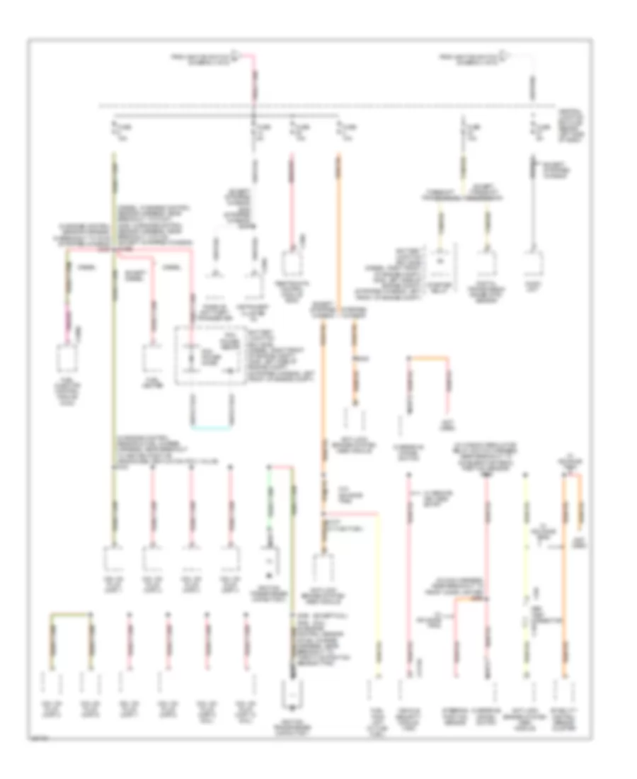
Power Distribution Wiring Diagram (6 of 6) for Ford Econoline E250 2008
List of elements for Power Distribution Wiring Diagram (6 of 6) for Ford Econoline E250 2008:
- (gas: in engine control sensor harness, near breakout to g101) (diesel: in engine control sensor harness, near breakout to c1019) (except stripped chassis) s1022
- (in window regulator relay switch harness, near breakout to c237) (w/ remote keyless entry) s246
- (not used)
- 16-way stripped chassis connector
- Battery charge trailer tow relay
- Battery junction box (bjb) (diesel: right front of engine compt) (gas: left side of engine compt) (stripped chassis: left front of engine compt)
- Brake pedal position switch
- C2113a
- C220b
- Central junction box (cjb) (behind left side of dash)
- Except stripped chassis
- From fuse 11 (diagram 3 of 6)
- From ignition switch (diagram 4 of 6)
- Fuse 15a
- Fuse 5a
- Instrument cluster (ic)
- Multi- function switch
- S256 (stripped chassis)
- S282 (in main harness, near breakout to electronic flasher module)
- Stripped chassis
- Vehicle security module (vsm)
- W/ remote keyless entry
- Windshield wiper motor