POWER DISTRIBUTION
Power Distribution Wiring Diagram (1 of 7) for Ford Edge Sport 2014

List of elements for Power Distribution Wiring Diagram (1 of 7) for Ford Edge Sport 2014:
- (left side of engine compt) battery junction box (bjb)
- (left side of engine compt) high current battery junction box (bjb)
- (main wiring harness, near breakout to hvac module) s207
- Anti-lock brake system (abs) module
- Battery
- Battery junction box (bjb) (left side of engine compt)
- Blower motor relay
- C110
- C1617a
- C1617b
- C212
- C215
- C228b
- C300
- C3036a
- C3053
- C316
- C3162a
- C4174a
- Console 2 power point
- Cooling fan module
- Datc hvac module (edge w/ heated seats)
- Dual climate controlled seat module (dcsm) (mkx w/ climate controlled seats)
- From fuse 28 a (diagram 1 of 7)
- Fuse 10a
- Fuse 15a
- Fuse 20a
- Fuse 25a
- Fuse 30a
- Fuse 40a
- Fuse 40a 60a
- G205 (right center of dash)
- Generator
- Generator current sensor
- Left rear heated seat module
- Liftgate/ trunk module (ltm)
- Mega 1 fuse 200a
- Mega 2 fuse 120a
- Nca
- Parking lamp trailer tow relay
- Rear console power point
- Rear washer relay
- Rear window defrost relay
- Red
- S112 (w/ trailer tow) (dash panel wiring harness, to headlight junction, near breakout to cooling fan module)
- S182
- S349
- Starter motor
- Starter relay
- To body control module (bcm) (diagram 3 of 7)
- To fuse 18 (diagram 1 of 7)
- To fuse 86 (diagram 2 of 7)
- Transmission control module (tcm) (2.0l turbo)
- W/ trailer tow
- W/o trailer tow
Power Distribution Wiring Diagram (2 of 7) for Ford Edge Sport 2014
List of elements for Power Distribution Wiring Diagram (2 of 7) for Ford Edge Sport 2014:
- (dash panel to headlight junction wiring harness, near breakout to c140) s117
- (dash panel to headlight junction wiring harness, near breakout to cooling fan module) s113
- (engine control sensor & fuel charge wiring harness, near breakout to fuel injector 3) s128
- (engine control sensor & fuel charge wiring harness, near breakout to fuel injector 3) s131
- (engine control sensor & fuel charge wiring harness, near breakout to powertrain control module) s124
- (if equipped)
- (left side of engine compt) battery junction box (bjb)
- 2.0l
- A/c clutch relay
- All wheel drive (awd) relay module
- Battery junction box (bjb) (left side of engine compt)
- Brake pedal position (bpp) switch
- C140
- C175b
- C210
- C212
- C215
- C925
- Cargo area power point
- Coil on plug (cop) 1
- Coil on plug (cop) 2
- Coil on plug (cop) 3
- Coil on plug (cop) 4
- Coil on plug (cop) 5
- Coil on plug (cop) 6
- Evap canister vent valve
- Evaporative emission (evap) purge valve
- Except 2.0l turbo turbo
- From c fuse 62 (diagram 2 of 7)
- From fuse 9 b (diagram 1 of 7)
- Fuel pump relay
- Fuse 10a
- Fuse 15a
- Fuse 20a
- Fuse 7.5a
- G205 (right center of dash)
- G400 (left "d" pillar)
- Heated oxygen sensor (ho2s) 12
- Heated oxygen sensor (ho2s) 22
- Instrument panel power point
- Left headlamp (w/ hid)
- Left turn trailer tow relay
- Mass air flow/intake air temperature (maf/iat) sensor
- Nca
- Pcm power relay (except 2.0l turbo)
- Powertrain control module (pcm)
- Rear seat release relay
- Rear window wiper motor
- Red
- Right headlamp (w/ hid)
- Right turn trailer tow relay
- Roof opening panel motor assembly
- S402
- Stop lamp relay (edge)
- To fuse 65 (diagram 2 of 7)
- To fuse 87 (diagram 3 of 7)
- To pcm power relay (diagram 7 of 7)
- Universal heated oxygen sensor (ho2s) 11
- Universal heated oxygen sensor (ho2s) 21
- Variable camshaft timing 11 (vct11) solenoid
- Variable camshaft timing 12 (vct12) solenoid
- Variable camshaft timing 21 (vct21) solenoid
- Variable camshaft timing 22 (vct22) solenoid
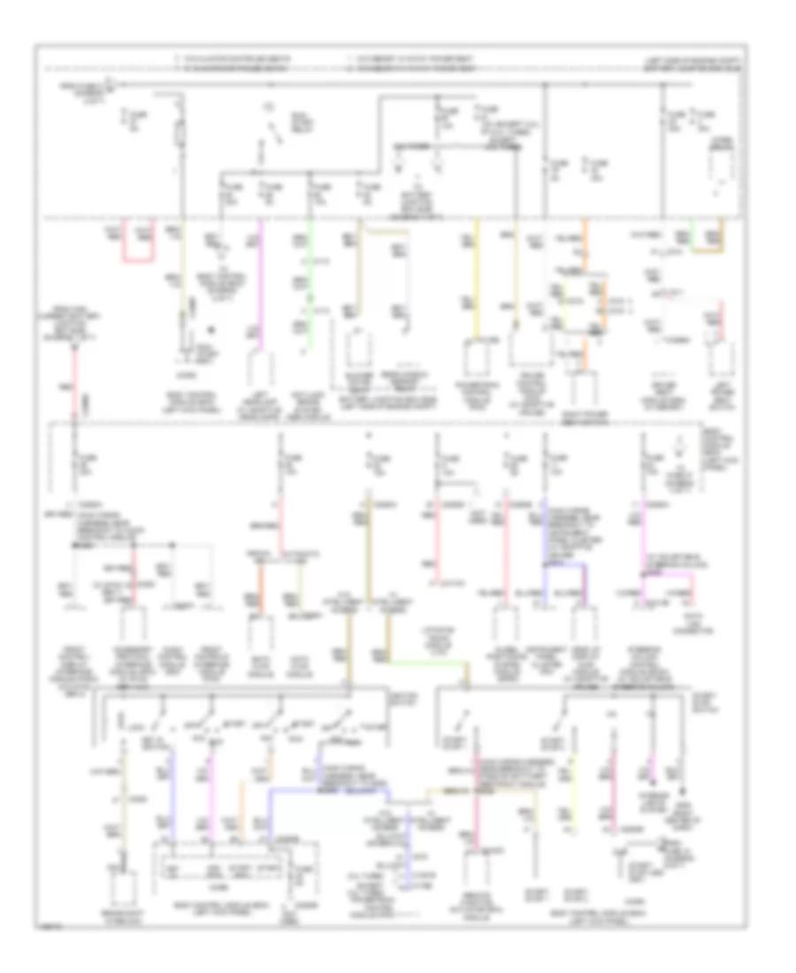
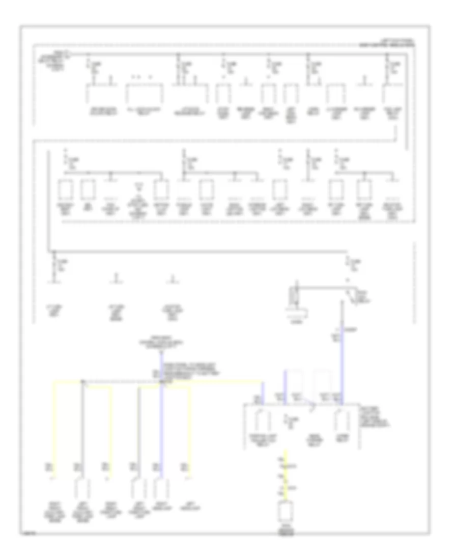
Power Distribution Wiring Diagram (3 of 7) for Ford Edge Sport 2014
List of elements for Power Distribution Wiring Diagram (3 of 7) for Ford Edge Sport 2014:
- (2.0l turbo)
- (except 2.0l)
- (left side of engine compt) battery junction box (bjb)
- (not used)
- (w/ adjustable steering column) s228
- (w/ sync gen 1)
- 2.0l turbo
- Acc
- Acc/ run
- Accessory protocol interface module (apim) (w/ sync gen 1 & 2)
- Anti-lock brake system (abs) module
- Audio control module (acm)
- Automatic a/c
- Battery junction box (bjb) (left side of engine compt)
- Blower motor relay
- Body control module (bcm) (left kick panel)
- Brake shift interlock
- C110
- C1381b
- C175b
- C212
- C215
- C2153c
- C2280a
- C2280b
- C2280d
- C2280f
- C2280g
- C228a
- C240a
- C2414b
- C3053
- C311
- C315
- C316
- C3299a
- C4174a
- Cruise control module (ccm) (w/ adaptive cruise)
- Data link connector
- Datc hvac module
- Driver seat module (dsm) (w/ memory)
- Emtc hvac module
- Except 2.0l turbo
- From fuse 18 (diagram 6 of 7)
- From fuse 21 d (diagram 2 of 7)
- From high current battery junction box (bjb) (diagram 1 of 7)
- Front control/ display interface module (fcdim) (w/o sync gen 2)
- Front controls interface module (fcim)
- Fuse 10a
- Fuse 10a 5a
- Fuse 15a
- Fuse 20a
- Fuse 30a
- Fuse 5a
- G205 (right center of dash)
- Global positioning system module (gpsm)
- Harness, near breakout to g205) s285
- Head up display (hud) module (w/ adaptive cruise)
- Ignition switch
- Instrument panel cluster (ipc)
- Interior lights system
- Key in
- Key in ignition
- Left headlamp (w/ adaptive headlamps)
- Left power seat switch
- Liftgate/ trunk module (ltm)
- Lock
- Manual a/c
- Micro
- Nca
- Off
- Passive anti-theft restraint module) s238
- Powertrain control module (pcm)
- Rear window defrost relay
- Red
- Remote function actuator (rfa) module
- Right power seat switch
- Run
- Run/ start (fet)
- Run/ start relay
- Start
- Start/ run
- Start/ stop (led) (fet)
- Start/ stop 1
- Start/ stop 2
- Start/ stop switch
- Steering column control module (sccm) (w/ adjustable steering column)
- To battery junction box (bjb) (diagram 7 of 7)
- To body control module (bcm) (diagram 5 of 7)
- To fuse 27 (diagram 4 of 7)
- W/ climate controled seats
- W/ intelligent access
- W/o climate controled seats
- W/o intelligent access
- W/o memory w/ 10-way power seat
- W/o memory w/ 6-way power seat
- Wiper relay
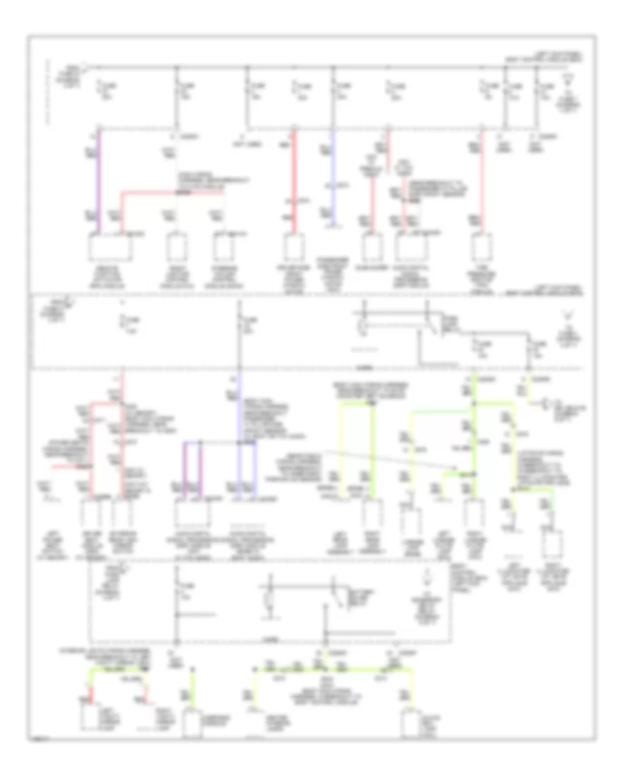
Power Distribution Wiring Diagram (4 of 7) for Ford Edge Sport 2014
List of elements for Power Distribution Wiring Diagram (4 of 7) for Ford Edge Sport 2014:
- (body main wiring harness, near breakout passenger "c" pillar side impact sensor) (w/ sony or thx audio) s339
- (body main wiring harness, near breakout to evap canister vent solenoid) s321
- (edge)
- (interior lights wiring harness, near breakout to left vanity mirror light) s901
- (left kick panel) body control module (bcm)
- (main wiring harness, near breakout to hvac module) s229
- (mkx w/ memory)
- (mkx w/o memory & edge)
- (mkx)
- (near breakout to passenger "c" pillar side impact sensor) s360
- (not used)
- (power seats wiring harness, near breakout to c311) s322
- (rear fascia wiring harness, near breakout to inner right parking aid sensor)
- Audio digital signal processing (dsp) module
- Audio digital signal processing (dsp) module (edge w/ sony audio)
- Audio digital signal processing (dsp) module (mkx w/ thx audio)
- Battery saver relay
- Body control module (bcm) (left kick panel)
- C210
- C213
- C2153c
- C2280a
- C2280d
- C2280e
- C2280f
- C2414a
- C311
- C3299b
- C406
- C4326c
- C4348c
- C510
- C610
- C919
- Center interior lamps
- Driver seat module (dsm) (w/ memory)
- Driver side front power window motor
- Exterior rear view mirror switch
- From f fuse 24 (diagram 3 of 7)
- From g fuse 21 (diagram 4 of 7)
- From h park lamp relay (diagram 4 of 7)
- Front lighting control module (flm)
- Fuse 10a
- Fuse 15a
- Fuse 20a
- Fuse 30a
- Fuse 5a
- Fuse 7.5a
- Glove box lamp (mkx)
- Left license plate lamp (mkx)
- Left power seat switch (w/ memory)
- Left rear lamp assembly
- Left vanity mirror lamp
- License lamp (edge)
- Micro
- Mkx w/ premium audio
- Mkx w/ thx audio
- Nca
- Overhead console
- Park lamp relay
- Passenger side front power window motor (mkx)
- Red
- Remote function actuator (rfa) module
- Right license plate lamp (mkx)
- Right rear lamp assembly
- Right vanity mirror lamp
- S234 (mkx) (body main wiring harness, in breakout to body control module)
- S413
- Steering column control module (sccm)
- Subwoofer
- Tire pressure monitor (tpm) module
- To accessory delay relay (diagram 5 of 7)
- To fuse 4 (diagram 4 of 7)
- To fuse 7 (diagram 4 of 7)
- To splice s109 (diagram 6 of 7)
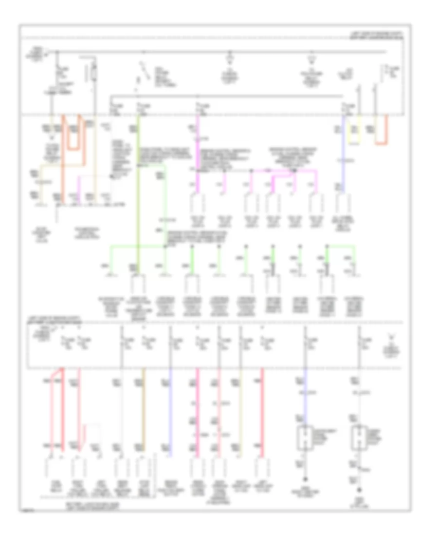
Power Distribution Wiring Diagram (5 of 7) for Ford Edge Sport 2014
List of elements for Power Distribution Wiring Diagram (5 of 7) for Ford Edge Sport 2014:
- (body main wiring harness, near breakout to c311) s308
- (body main wiring harness, near breakout to c510) (edge) s254
- (body main wiring harness, near breakout to g200) s382
- (edge)
- (left kick panel) body control module (bcm)
- (mkx)
- (not used)
- (right front window regulator wiring harness near breakout to right exterior rear view mirror switch) (mkx) s607
- (w/ blind spot information system system (blis))
- Accessory delay relay
- Air inlet mode door actuator (except 2.0l turbo)
- Auto-dimming interior mirror
- Body control module (bcm) (left kick panel)
- Brake shift interlock (2.0l turbo)
- C210
- C2280a
- C2280b
- C2280d
- C2280e
- C264
- C300
- C3053
- C310a
- C314
- C495
- C504a
- C510
- C535a
- C535b
- C610
- C919
- Circuit breaker 30a
- Driver side door lock switch (edge)
- Driver side front power window motor
- From battery junction box j (bjb) (diagram 3 of 7)
- From m fuse 4 (diagram 4 of 7)
- Fuse 10a
- Fuse 15a
- Fuse 5a
- Fuse 7.5a
- Head up display (hud) module (w/ adaptive cruise control)
- Heated steering wheel module (hswm)
- Left rear heated seat module
- Left side obstacle detection control module
- Master window adjust switch
- Master window adjust switch (mkx)
- Micro
- Nca
- Occupant classification system module (ocsm)
- Parking aid module (pam)
- Passenger side door lock switch (edge)
- Passenger side front power window motor (mkx)
- Passenger side window adjust switch (edge)
- Passenger side window adjust switch (mkx)
- Restraints control module (rcm)
- Right side obstacle detection control module
- Roof opening panel motor assembly (if equipped)
- To fuse 20 (diagram 6 of 7)
- Video camera
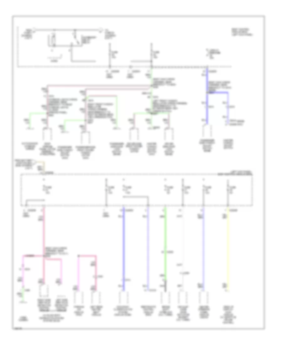
Power Distribution Wiring Diagram (6 of 7) for Ford Edge Sport 2014
List of elements for Power Distribution Wiring Diagram (6 of 7) for Ford Edge Sport 2014:
- (left kick panel) body control module (bcm)
- 2nd row seat (fet)
- All lock/unlock relay
- Back lighting led (fet)
- Battery junction box (bjb) (left side of engine compt)
- Bsi (fet)
- C210
- C212
- C2280f
- Delay relay (diagram 5 of 7)
- Driver door unlock relay
- Fog lamp relay (mkx)
- From accessory k
- From body control module (bcm) (diagram 4 of 7)
- Fuse 10a
- Fuse 15a
- Fuse 20a
- Fuse 5a
- Horn relay
- Interior lighting (fet)
- Keypad illum (fet)
- Left front auxiliary park lamp (edge)
- Left front park/turn lamp
- Left headlamp
- Left high beam (fet)
- Left low beam (fet)
- Lf turn lamp (fet)
- Lh corner lamp (fet)
- Liftgate release relay
- Lr stop/ turn lamp (fet) (mkx)
- Lr turn lamp (fet) (edge)
- Micro
- Parking lamp trailer tow relay
- Pcm wake up (fet)
- Puddle lamp (fet)
- Rain sensor module
- Rear washer relay
- Reverse lamp (fet)
- Rf turn lamp (fet)
- Rh corner lamp (fet)
- Right front auxiliary park lamp (edge)
- Right front park/turn lamp
- Right headlamp
- Right high beam (fet)
- Right low beam (fet)
- Rr stop/ turn lamp (fet) (mkx)
- Rr turn lamp (fet) (edge)
- Run/ acc relay
- Stop/ chmsl (fet)
- To start/ stop (led) fet (diagram 3 of 7)
- White light (fet)
- Wiper relay
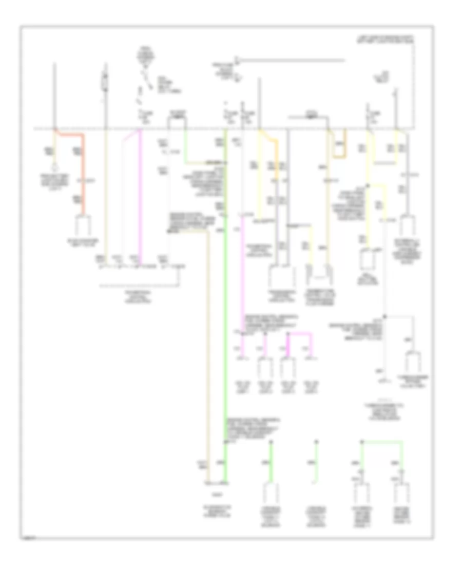
Power Distribution Wiring Diagram (7 of 7) for Ford Edge Sport 2014
List of elements for Power Distribution Wiring Diagram (7 of 7) for Ford Edge Sport 2014:
- (engine control sensor & fuel charge wiring harness, near breakout to c140) s169
- (engine control sensor & fuel charge wiring harness, near breakout to coil on plug 1) s175
- (engine control sensor & fuel charge wiring harness, near breakout to variable camshaft timing 11 solenoid) s173
- (left side of engine compt) battery junction box (bjb)
- A/c clutch relay
- Atwu diode
- C110
- C1381b
- C1381e
- C140
- C212
- Coil on plug (cop) 1
- Coil on plug (cop) 2
- Coil on plug (cop) 3
- Coil on plug (cop) 4
- Evap conister vent valve
- Evapcp diode
- Evaporative emission purge valve
- Externally controlled variable displacement compressor (evdc)
- From battery junction box bjb) (diagram 2 of 7)
- From fuse 62 (diagram 2 of 7)
- Fuse 10a
- Fuse 15a
- Fuse 20a
- Grill shutter actuator
- Heated oxygen sensor (ho2s) 12
- Nca
- P from fuse 90 & 91 (diagram 3 of 7) o
- Pcm power relay (2.0l turbo)
- Powertrain control module (pcm)
- S108 (dash panel to headlight junction wiring harness, near breakout to battery junction box)
- S118 (dash panel to headlight junction wiring harness, near breakout to anti-theft hood switch)
- S172 (engine control sensor & fuel charge wiring harness, near breakout to c140)
- S181
- Temperature control valve transmission fluid warmer
- Transmission control module (tcm)
- Turbocharger (tc) wastegate regulating valve solenoid
- Turbocharger bypass valve (tcby)
- Universal heated oxygen sensor (ho2s) 11
- Variable camshaft timing 11 (vct11) solenoid
- Variable camshaft timing 12 (vct12) solenoid