POWER DISTRIBUTION
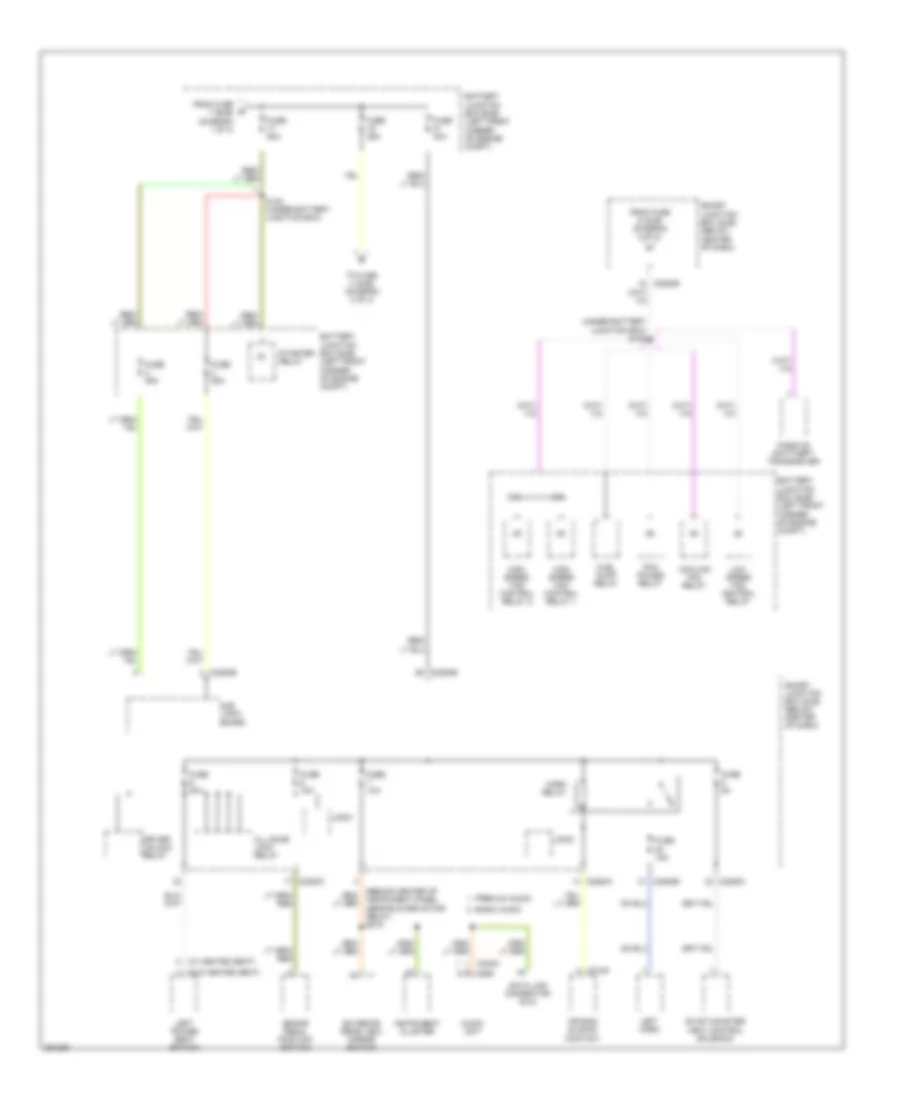
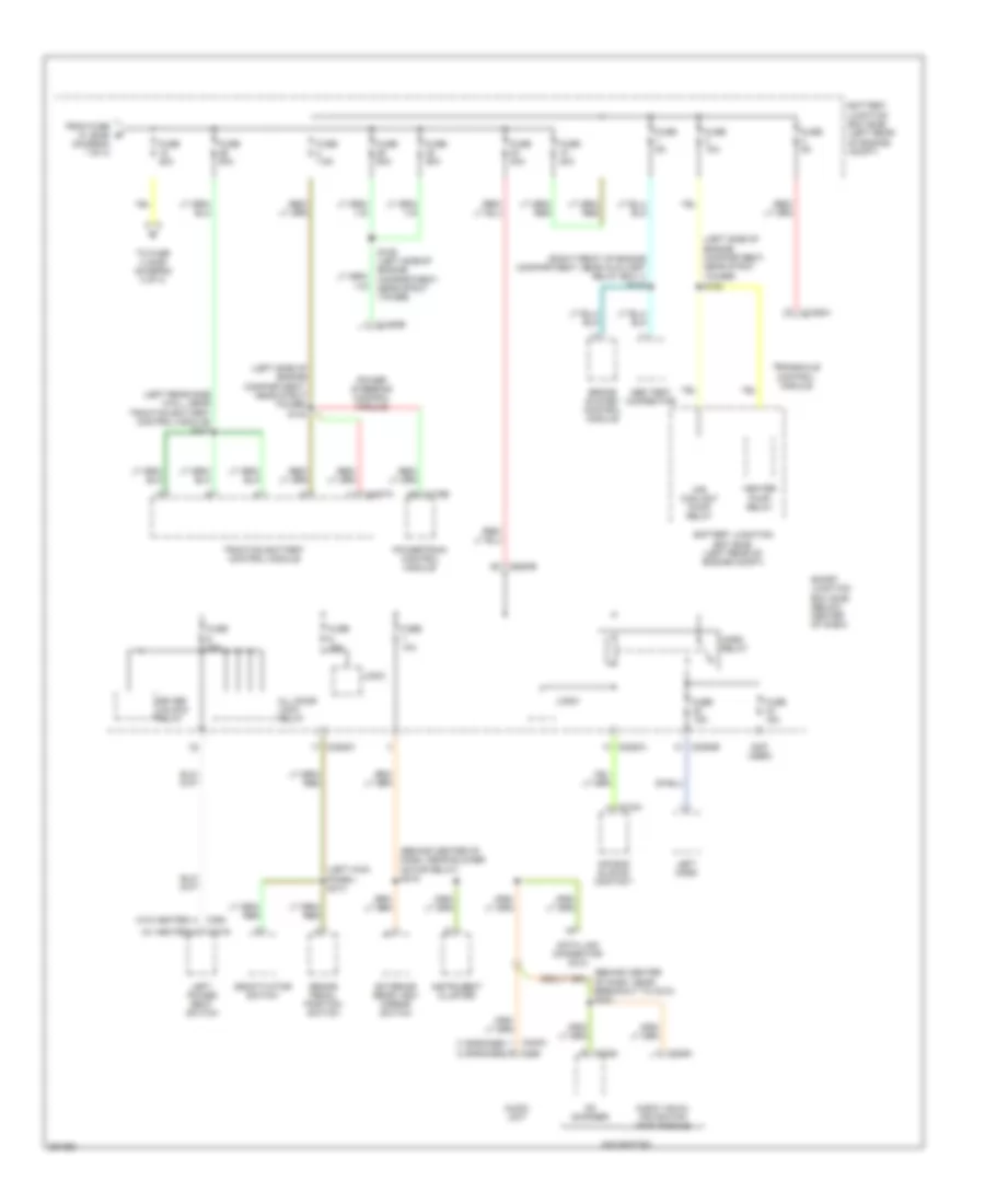
Power Distribution Wiring Diagram, Except Hybrid (1 of 4) for Ford Escape Hybrid 2007

List of elements for Power Distribution Wiring Diagram, Except Hybrid (1 of 4) for Ford Escape Hybrid 2007:
- (2.3l)
- (3.0l)
- (3.0l) (2.3l)
- (left front corner of engine compt) battery junction box (bjb)
- (left front corner of engine compt) s196
- (left rocker panel, near driver's seat)
- (not used)
- (under battery junction box) s144
- 2.3l
- 3.0l
- 87a
- A/c clutch relay
- Abs control module
- Abs test connector
- Battery
- Battery junction box (bjb) (left front corner of engine compt)
- Blower motor relay
- C102a
- C102b
- C102c
- C1035a
- C1035c c1035b
- C197a
- C2280b
- C2280c
- Cooling fan relay
- Driver side exterior rear view mirror
- Fog lamp relay
- From fuse 7 (bjb) (diagram 1 of 4)
- Fuel pump relay
- Fuse (2.3l) 40a
- Fuse (3.0l) 50a
- Fuse 10a
- Fuse 15a
- Fuse 20a
- Fuse 30a
- Fuse 40a
- Fuse 5a
- Fuse 60a
- G206 (behind left side of dash)
- Generator
- Heated seats relay
- High speed fan control relay 1
- Logic
- Lom
- Low speed fan control relay
- Park lamp relay
- Passenger side exterior rear view mirror
- Pcm power relay
- Power point
- Powertrain control module (pcm)
- Rear defrost relay
- Rear window defrost grid
- Rear window defrost switch
- Red
- S198
- S199 (left side of engine compt near battery junction box)
- S214
- S330
- Smart junction box (sjb) (below center of dash)
- Starter motor
- To accessory delay relay (sjb) (diagram 3 of 4)
- To accessory relay (sjb) (diagram 3 of 4)
- To fuse 17 (bjb) (diagram 2 of 4)
- To fuse 20 (bjb) (diagram 1 of 4)
- Trailer tow connector
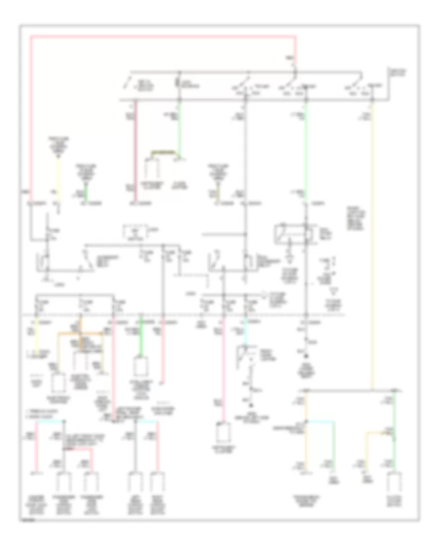
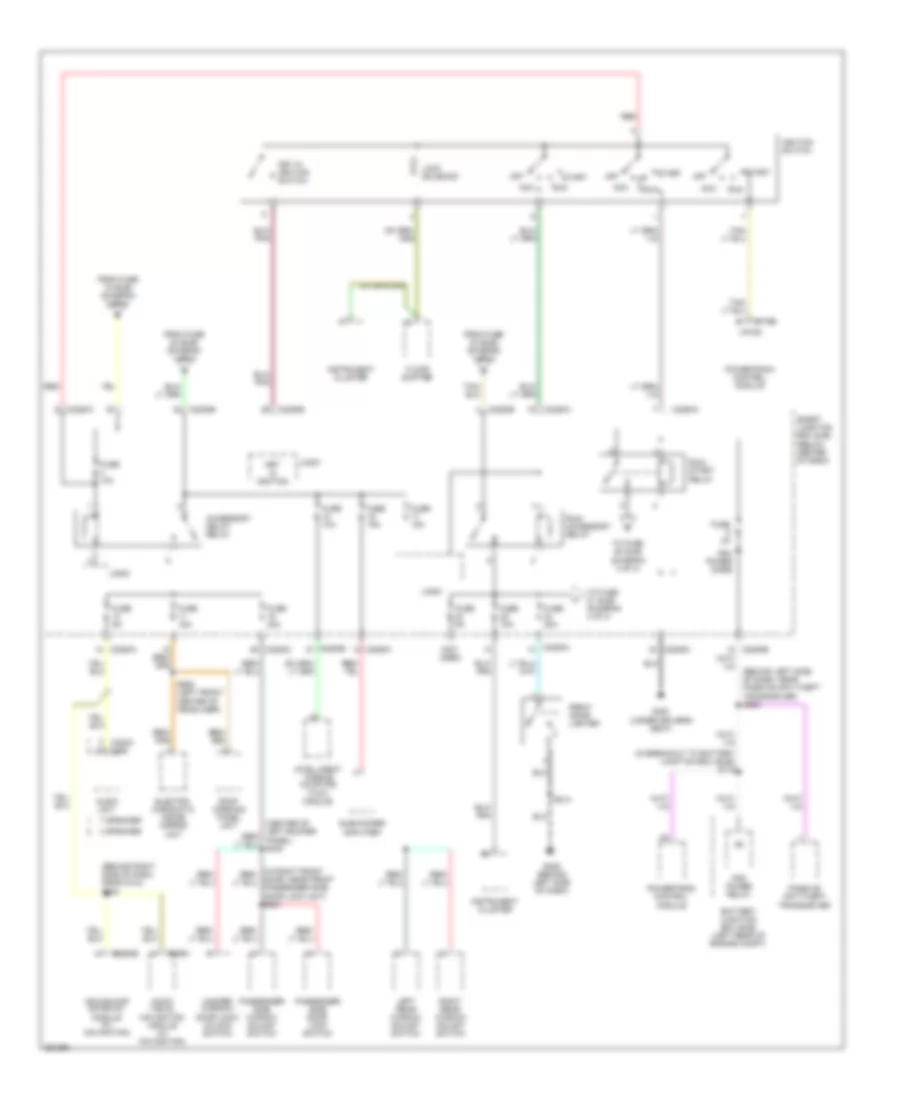
Power Distribution Wiring Diagram, Except Hybrid (2 of 4) for Ford Escape Hybrid 2007
List of elements for Power Distribution Wiring Diagram, Except Hybrid (2 of 4) for Ford Escape Hybrid 2007:
- (under battery junction box) s128
- (w/ heated seat) h
- (w/o heated seat)
- 2.3l
- 3.0l
- Air bag sliding contact
- All door lock relay
- Audio unit
- Basic audio
- Battery junction box (bjb) (left front corner of engine compt)
- Brake pedal position switch
- C218a
- C2280a
- C2280b
- C2280c
- C240a
- C290
- Cooling fan relay
- Data link connector (dlc)
- Driver unlock relay
- Evap canister vent control solenoid
- Exterior rear view mirror switch
- From fuse 5 (sjb) (diagram 3 of 4)
- From fuse 7 (bjb) (diagram 1 of 4)
- Fuel pump relay
- Fuse 10a
- Fuse 15a
- Fuse 25a
- Fuse 30a
- Fuse 40a
- Fuse 50a
- Fuse 5a
- High speed fan control relay 1
- High speed fan control relay 2
- Horn relay
- Instrument cluster
- Left horn
- Left power seat switch
- Logic
- Low speed fan control relay
- Passive anti-theft transceiver
- Pcm power relay
- Premium audio
- S130 (under battery junction box)
- Sjb logic board
- Smart junction box (sjb) (below center of dash)
- Starter relay
- To fuse 4 (sjb) (diagram 3 of 4)
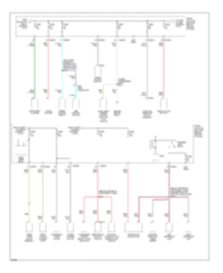
Power Distribution Wiring Diagram, Except Hybrid (3 of 4) for Ford Escape Hybrid 2007
List of elements for Power Distribution Wiring Diagram, Except Hybrid (3 of 4) for Ford Escape Hybrid 2007:
- (in left front door near breakout to door lock unit) s601
- (not used)
- A/t
- Acc
- Accessory delay relay
- Audio unit
- Basic audio
- C2280a
- C2280b
- C2280c
- C2280e
- C240a
- C290
- Clutch cutoff switch
- Driver's seat)
- Electro- chromatic inside mirror
- Electronic compass
- Floor shifter
- From fuse 1 (bjb) (diagram 2 of 4)
- From fuse 19 (bjb) (diagram 1 of 4)
- From fuse 7 (bjb) (diagram 1 of 4)
- Front cigar lighter
- Fuse 10a
- Fuse 15a
- Fuse 20a
- Fuse 2a
- Fuse 30a
- Fuse 5a
- G206 (behind left side of dash)
- G300 (under
- Ignition switch
- Instrument cluster
- Intelligent torque coupling (itcc) module
- Key in ignition
- Key in ignition switch
- Left rear window adjust switch
- Lock solenoid
- Logic
- M/t
- Master window/ door lock/ unlock switch
- Off
- Passenger side door lock switch
- Passenger side window adjust switch
- Pcm power diode
- Premium audio
- Red
- Right rear window adjust switch
- Roof opening panel unit
- Run
- Run/ accessory relay
- Run/ start relay
- S113 (near breakout to c260)
- S214
- S332
- Smart junction box (sjb) (below center of dash)
- Start
- Subwoofer amplifier
- To (sjb) diagram 2 of 4)
- To fuse 21 (sjb) (diagram 4 of 4)
- To fuse 28 (sjb) (diagram 4 of 4)
- Transmission range (tr) sensor
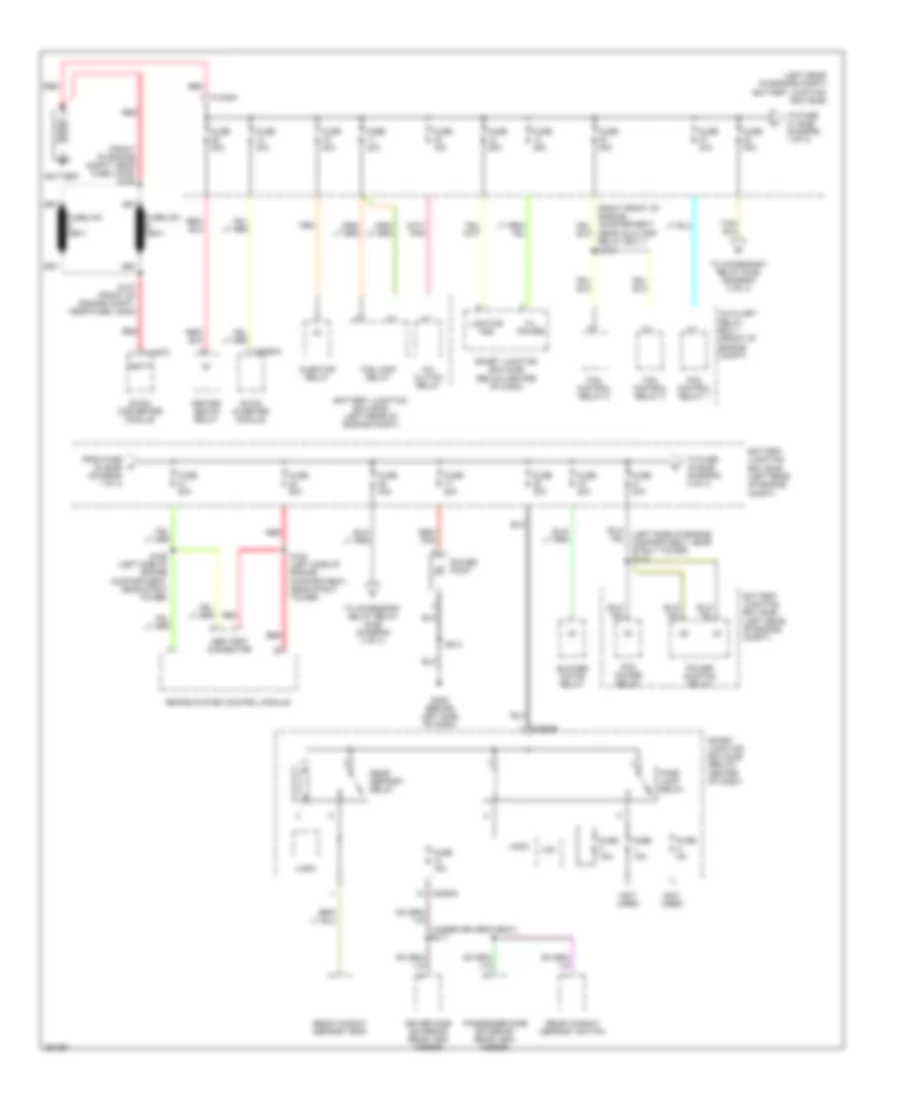
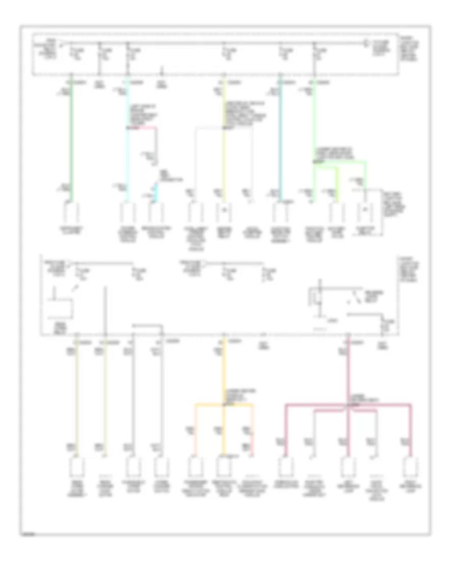
Power Distribution Wiring Diagram, Except Hybrid (4 of 4) for Ford Escape Hybrid 2007
List of elements for Power Distribution Wiring Diagram, Except Hybrid (4 of 4) for Ford Escape Hybrid 2007:
- (behind center of instrument panel)
- (below center of instrument panel, near restraints control module (rcm) s333
- (left front corner of engine compt near battery junction box) s119
- (not used)
- (under passenger's seat) s301
- Abs control module
- Abs test connector
- Air bag sliding contact
- Assembly
- C2041a
- C218a
- C2208d
- C2280a
- C2280b
- C2280c
- C2280d
- C294a
- Deactivator switch
- Electro- chromatic inside mirror
- Floor shifter
- From fuse 26 (sjb) (diagram 4 of 4)
- From fuse h 24 (sjb) (diagram 3 of 4)
- From run/start g
- Function selector switch
- Fuse 10a
- Fuse 15a
- Fuse 20a
- Fuse 5a
- Heated seats relay
- Instrument cluster
- Intelligent torque control coupling (itcc) module
- Left reversing lamp
- Logic
- Occupant classification sensor (ocs) module
- Parking aid module (pam)
- Passenger air bag deactivation indicator
- Rear window washer pump
- Rear wiper motor assembly
- Rear wiper relay
- Relay (diagram 3 of 4)
- Restraints control module
- Reverse lamp relay
- Right reversing lamp
- S204
- Smart junction box (sjb) (below center of dash)
- Speed control servo
- To fuse 33 (sjb) (diagram 4 of 4)
- Windshield wiper motor
- Wiper/ washer switch
Power Distribution Wiring Diagram, Hybrid (1 of 4) for Ford Escape Hybrid 2007
List of elements for Power Distribution Wiring Diagram, Hybrid (1 of 4) for Ford Escape Hybrid 2007:
- (front of engine compt, near fuse links) s128
- (left rear of engine compt) battery junction box (bjb)
- (left side of engine compartment, near strut tower) s110
- (not used)
- (under driver's seat) s317
- A/c clutch relay
- Abs test connector
- Auxiliary relay box 1 (front of engine compt)
- Battery
- Battery junction box (bjb) (left rear of engine compt)
- Blower motor relay
- Brake system control module
- C1035a
- C1457c
- C2280b
- C2280c
- C2293a
- Dc/ac inverter module
- Dc/dc converter module
- Driver side exterior rear view mirror
- Fan control relay 1
- Fan control relay 2
- Fan control relay 3
- Fog lamp relay
- From fuse 30 (bjb) (diagram 1 of 4)
- Fuse 15a
- Fuse 20a
- Fuse 25a
- Fuse 30a
- Fuse 40a
- Fuse 50a
- Fuse 5a
- G206 (behind left side of dash)
- H/l power
- Heated seats relay
- Injector relay
- Lighting hsd
- Logic
- Lom
- Near auxiliary relay box 1) s134
- Park lamp relay
- Passenger side exterior rear view mirror
- Pcm power relay
- Power point
- Power sustain relay
- Rear defrost relay
- Rear window defrost grid
- Rear window defrost switch
- Red
- S124 (left side of engine compartment, near strut tower)
- S126 (left side of engine compartment, near strut tower)
- S127 (front of engine compt, near fuse links)
- S214
- Smart junction box (sjb) (below center of dash)
- To accessory delay relay (sjb) (diagram 3 of 4)
- To accessory relay (sjb) (diagram 3 of 4)
- To fuse 15 (bjb) (diagram 2 of 4)
- To fuse 31 (bjb) (diagram 1 of 4)
- Vbatt
Power Distribution Wiring Diagram, Hybrid (2 of 4) for Ford Escape Hybrid 2007
List of elements for Power Distribution Wiring Diagram, Hybrid (2 of 4) for Ford Escape Hybrid 2007:
- (4 speaker)
- (7 speaker)
- (behind center of dash, near breakout to c210) s243
- (behind center of dash, near blower motor relay) s216
- (left kick panel) s314
- (left rear side wall, near traction battery control module) s417
- (left side of engine compartment, near strut tower)
- (not used)
- (right front of engine compartment, near auxiliary relay box 1) s135
- (w/o heated)
- Abs test connector
- Air bag sliding contact
- All door lock relay
- Audio unit
- Audio visual navigation (avn) module
- Battery junction box (bjb) (left rear of engine compt)
- Brake pedal position switch
- Brake system control module
- C1458a
- C1463b
- C175b
- C218a
- C2280a
- C2280b
- C2280c
- C229a
- C240a
- C290
- C3016
- C3028
- C352
- C4227a
- Cd changer
- Data link connector (dlc)
- Deactivator switch
- Driver unlock relay
- Exterior rear view mirror switch
- From fuse 21 (bjb) (diagram 1 of 4)
- Fuse 10a
- Fuse 15a
- Fuse 20a
- Fuse 30a
- Fuse 40a
- Fuse 50a
- Fuse 5a
- Fuse 7.5a
- H (w/ heated)
- Heater pump relay
- Horn relay
- Instrument cluster
- Left horn
- Left power seat switch
- Logic
- M/e coolant pump relay
- Navigation
- Power steering control module
- Powertrain control module
- S109 (left side of engine compartment, near strut tower)
- S130
- S152
- Smart junction box (sjb) (below center of dash)
- To fuse 4 (sjb) (diagram 3 of 4)
- Traction battery control module
- Transaxle control module
Power Distribution Wiring Diagram, Hybrid (3 of 4) for Ford Escape Hybrid 2007
List of elements for Power Distribution Wiring Diagram, Hybrid (3 of 4) for Ford Escape Hybrid 2007:
- (behind right side of dash, near c212) s240
- (in breakout to battery junction box (bjb)) s115
- (not used)
- 4 speaker
- 7 speaker
- Acc
- Accessory delay relay
- Audio unit
- Audio visual navigation module (w/ navigation)
- Battery junction box (bjb) (left rear of engine compt)
- C175b
- C2280a
- C2280b
- C2280c
- C2280e
- C2294b
- C229a
- C240a
- C290
- Electro- chromatic inside mirror unit
- Floor shifter
- From fuse 15 (bjb) (diagram 2 of 4)
- From fuse 22 (bjb) (diagram 1 of 4)
- From fuse 30 (bjb) (diagram 1 of 4)
- Front cigar lighter
- Fuse 10a
- Fuse 15a
- Fuse 20a
- Fuse 2a
- Fuse 30a
- Fuse 5a
- G206 (behind left side of dash)
- G300 (under driver's seat)
- Ignition switch
- Instrument cluster
- Intelligent torque coupling (itcc) module
- Key in ignition
- Key in ignition switch
- Left rear window adjust switch
- Lock solenoid
- Logic
- Master window/ door lock/ unlock switch
- Ms-can/acp gateway module (w/ navigation)
- Off
- Passenger side door lock switch
- Passenger side window adjust switch
- Passive anti-theft transceiver
- Pcm power diode
- Pcm power relay
- Powertrain control module
- Red
- Right rear window adjust switch
- Roof opening panel unit
- Run
- Run/ accessory relay
- Run/ start relay
- S214
- S905 (left front center of headliner)
- Smart junction box (sjb) (below center of dash)
- Start
- Subwoofer amplifier
- To fuse 21 (sjb) (diagram 4 of 4)
- To fuse 28 (sjb) (diagram 4 of 4)
- Vpwr
Power Distribution Wiring Diagram, Hybrid (4 of 4) for Ford Escape Hybrid 2007
List of elements for Power Distribution Wiring Diagram, Hybrid (4 of 4) for Ford Escape Hybrid 2007:
- (center of vehicle floor, near breakout for intelligent torque control coupling (itcc) module) s301
- (left side of engine compartment, near strut tower) s125
- (not used)
- (under center console, near c211) s204
- (under center of dash, near smart junction box (sjb)) s251
- (under driver's seat) s309
- Abs test connector
- Assembly
- Audio visual navigation (avn) module
- Battery junction box (bjb) (left rear of engine compt)
- Battery zone valve
- Brake system control module
- C2041a
- C2208d
- C2280a
- C2280b
- C2280c
- C2280d
- C294a
- Dc/ac inverter module
- Electro- chromatic inside mirror unit
- From fuse 27 (sjb) (diagram 4 of 4)
- From fuse h 24 (sjb) (diagram 3 of 4)
- From run/start g
- Function selector switch
- Fuse 10a
- Fuse 15a
- Fuse 20a
- Fuse 5a
- Heated seats relay
- Injector relay
- Instrument cluster
- Intelligent torque control coupling (itcc) module
- Left reversing lamp
- Logic
- Occupant classification sensor (ocs) module
- Parking aid module (pam)
- Passenger air bag deactivation indicator
- Power steering control module
- Rear washer pump motor
- Rear wiper motor assembly
- Rear wiper relay
- Relay (diagram 3 of 4)
- Restraints control module (rcm)
- Reverse lamps relay
- Right reversing lamp
- Smart junction box (sjb) (below center of dash)
- To fuse 33 (sjb) (diagram 4 of 4)
- Traction battery control module
- Windshield wiper motor
- Wiper/ washer switch