POWER DISTRIBUTION
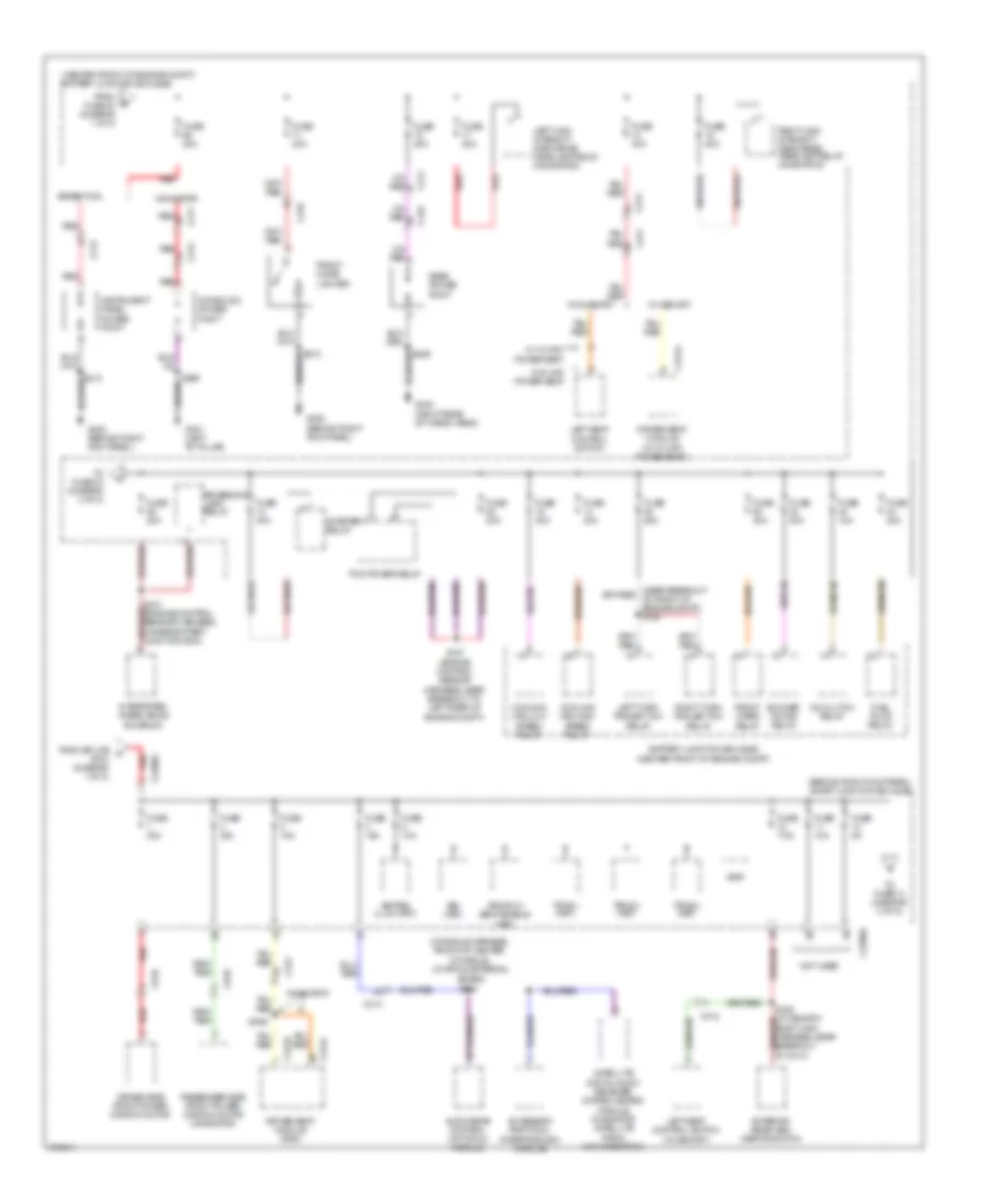
Power Distribution Wiring Diagram (1 of 5) for Ford Expedition 2012

List of elements for Power Distribution Wiring Diagram (1 of 5) for Ford Expedition 2012:
- (center front of engine compt) battery junction box (bjb)
- (expedition: engine control sensor harness, under battery junction box) (navigation: engine control sensor harness, near breakout for right headlight) s114
- (in engine harness, near right side of battery junction box (bjb))
- (in engine harness, near right side of battery junction box (bjb)) s148
- Air suspension compressor relay
- Anti-lock brake system (abs) module
- Auxiliary blower motor relay 1
- Auxiliary relay box 2 (right rear corner of vehicle)
- Battery
- Battery charge trailer tow relay
- Brake pedal position (bpp) switch
- C102a
- C139
- C175b
- C210
- C211
- C212
- C2131a
- C314
- C316
- C3265a f
- C3313b
- C410
- C4174a
- C465
- C816
- C922
- Console 1 power point
- Dual climate controlled seat module (dcsm)
- Evaporative emissions (evap) canister vent solenoid
- From splice s212 (diagram 4 of 5)
- Fuse 10a
- Fuse 20a
- Fuse 25a
- Fuse 30a
- Fuse 40a
- Fuse 5a
- Fuse 60a
- Fusible link d (10 ga- red)
- G100 (right side of engine compt)
- G101 (right side of engine compt)
- G102 (lower left side of engine)
- G107 (right rear of engine compt)
- Generator
- Nca
- Parking lamp trailer tow relay
- Power liftgate module
- Power running board (prb) module
- Powertrain control module (pcm)
- Rear window defrost relay
- Red
- Right seat control switch
- Roof opening panel module
- Run/ start relay
- S102
- S104 red (engine control sensor harness, near breakout to c140)
- S105 (engine control sensor harness, near breakout red to c140)
- S149
- S159 (in harness, near right side of battery junction box (bjb))
- S3005
- S369
- Sensor harness, left rear corner of engine compt)
- Starter motor
- Third row power-fold seat relay
- To fuse 1 smart junction box (sjb) (diagram 2 of 5)
- To fuse 52 (diagram 5 of 5)
- To fuse 55 (diagram 5 of 5)
- To fuse 65 (diagram 2 of 5)
- Trailer brake control module (tbc)
- Vehicle dynamics module (vdm)
- W/ 10-way power seat
- W/ 6-way power seat
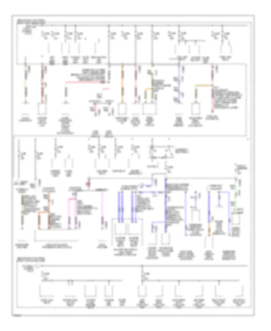
Power Distribution Wiring Diagram (2 of 5) for Ford Expedition 2012
List of elements for Power Distribution Wiring Diagram (2 of 5) for Ford Expedition 2012:
- (behind right kick panel) smart junction box (sjb)
- (center front of engine compt)
- (center front of engine compt) battery junction box (bjb)
- (console harness, front of center console) (w/ apim & external
- 3rd row seat enable (fet)
- A/c clutch relay
- Accessory protocol interface (aim) module
- Audio rear control unit (rcu) module
- Battery junction box (bjb)
- Blower motor relay
- Bsi (fet)
- C210
- C211
- C212
- C213
- C2280d
- C2280g
- C311
- C312
- C314
- C341a
- C341b
- C341c
- C410
- C510
- C610
- Console 2 power point
- Cooling fan high speed relay
- Cooling fan low speed relay
- Driver seat module (dsm)
- Driver seat module (w/ 10-way power seat)
- Driver side front power window motor
- Expedition
- Exterior rear view mirror switch
- From fuse 43 (diagram 1 of 5)
- From splice a s104 (diagram 1 of 5)
- Front cigar lighter
- Front wiper relay
- Fuel pump relay
- Fuse 10a
- Fuse 15a
- Fuse 20a
- Fuse 25a
- Fuse 30a
- Fuse 40a
- Fuse 5a
- Fuse 7.5a
- G200 (behind right kick panel)
- G301 (left "b" pillar)
- G402 (right rear of cargo area)
- Instrument panel power point
- Integrated wheel ends solenoid
- Keypad illum (fet)
- Left high intensity discharge headlamp relay (navigator)
- Left seat control switch
- Left seat control switch (w/ memory)
- Left turn trailer tow relay
- Navigator
- Not used
- Passenger side front power window motor (navigator)
- Pcm power relay
- Rear power point
- Red
- Reversing lamp relay
- Right high intensity discharge headlamp relay (navigator)
- Right turn trailer tow relay
- S121 (engine control sensor harness, under battery junction box)
- S127 (engine control sensor harness, near breakout to left rear of engine compt)
- S359
- S369
- Satellite digital audio receiver system (sdars) module (navigator satellite radio w/o navigation)
- Sdars) s382
- Starter relay
- To fuse 14 (diagram 3 of 5)
- To fuse 33 (diagram 4 of 5)
- Tpms 1 (fet)
- Tpms 2 (fet)
- Tpms 3 (fet)
- Vbat
- W/ 10-way power seat
- W/ 6-way power seat
- W/ memory
- W/o memory
Power Distribution Wiring Diagram (3 of 5) for Ford Expedition 2012
List of elements for Power Distribution Wiring Diagram (3 of 5) for Ford Expedition 2012:
- (behind right kick panel) smart junction box (sjb)
- (expedition: on rear dash harness, near breakout to climate control) (navigator: main harness, near breakout to c238) s266
- (rear light connector harness, near breakout to left side of loading space) (expedition) s400
- 25a
- Accessory delay relay
- Adjustable pedal switch (w/o memory)
- Audio amplifier
- Audio control module (acm)
- Audio digital signal processing (dsp) module
- Automatic a/c
- Auxiliary relay box 2 (right rear corner of vehicle)
- Backlighting led (fet)
- Battery saver relay
- C214
- C2280a
- C2280a (not used)
- C2280b
- C2280d
- C228a
- C2357a
- C2364a
- C2385b
- C240a
- C3054b
- C314
- C410
- C411
- C4174a
- C465
- C504a
- C510
- C535a
- C535b
- C610
- C922
- C935
- Circuit breaker 30a
- Clock (navigator)
- Control
- Data link connector
- Door lock relay
- Driver door unlock relay
- Driver side door lock switch (expedition)
- Driver side front power window motor
- Expedition
- Floor lamp (fet)
- Fog lamp relay
- From g fuse 13 (diagram 2 of 5)
- Fuse
- Fuse 10a
- Fuse 15a
- Fuse 20a
- Global positioning system
- High beam relay
- Horn relay
- Hvac (datc) module
- Hvac (emtc) module
- Instrument cluster (ic)
- Interior lighting (fet)
- Left front turn lamp (fet)
- Left low beam (fet)
- Left rear stop/ turn lamp (fet)
- Left rear turn lamp (fet)
- Liftgate glass release relay
- Liftgate rel (fet)
- Liftgate/ trunk module (ltm)
- Manual a/c
- Master window adjust switch
- Master window adjust switch (navigator)
- Module (gpsm) (w/ sync w/o navigation)
- Navigator
- Navigator w/ thx audio
- Near breakout to passenger's door) s601
- Park lamp relay
- Passenger side door lock switch (expedition)
- Passenger side front power window motor (navigator)
- Puddle lamp (fet)
- Pulse train (fet)
- Quarter window close relay
- Quarter window open relay
- Rear heated seat module
- Rear wiper motor assembly
- Right front turn lamp (fet)
- Right low beam (fet)
- Right rear stop/ turn lamp (fet)
- Right rear turn lamp (fet)
- Right side front power window switch (navigator)
- Roof opening panel module
- S209 (body main harness, near breakout to below right side of dash)
- S217 (w/o memory) (expedition: rear dash harness, near breakout to instrument cluster) (navigation: on rear dash harness, near breakout to instrument cluster)
- S236 (body main harness, near breakout to c2364c)
- Subwoofer amplifier
- To fuse 27 (diagram 4 of 5)
- To splice s208 (diagram 4 of 5)
- W/ premium sound
- White light (fet)
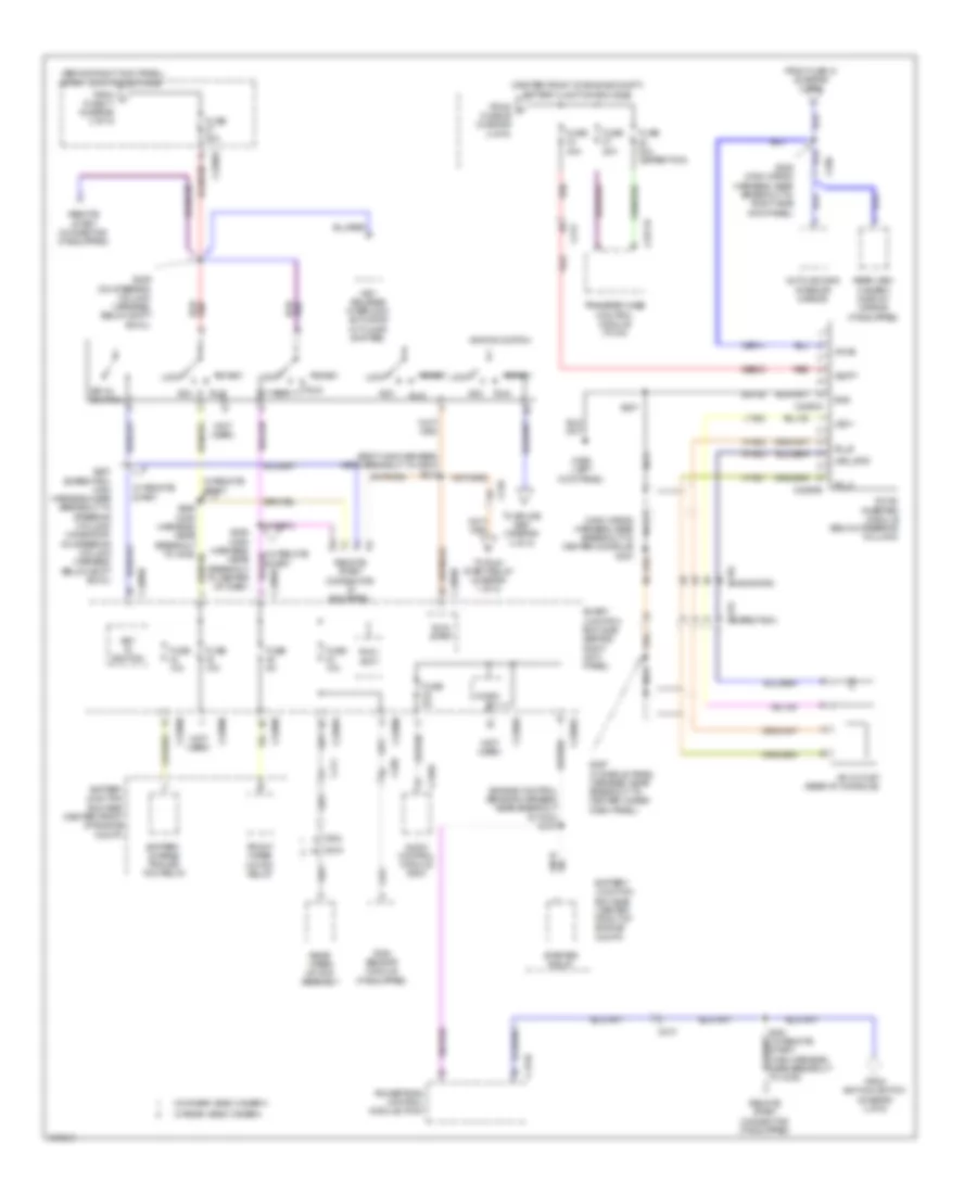
Power Distribution Wiring Diagram (4 of 5) for Ford Expedition 2012
List of elements for Power Distribution Wiring Diagram (4 of 5) for Ford Expedition 2012:
- (behind right kick panel) smart junction box (sjb)
- (body main harness, near breakout to g203) s212
- (center front of engine compt) battery junction box (bjb)
- (engine control sensor harness, near breakout to pcm) s107
- (expedition) c315
- (main wiring nca
- (navigator) c315
- (not used)
- A/c outlet (rear of console)
- Acc
- Ac_a
- Ac_b
- Audio control module (acm)
- Auto-dimming interior mirror
- Battery charge trailer tow relay
- Battery junction box (bjb) (center front of engine compt)
- C175b
- C210
- C213
- C2280a
- C2280b
- C2280d
- C2280e
- C2293a
- C2293b
- C2371b
- C240a
- C298
- C411
- C919
- C934
- Cbp41
- Dc/ac inverter module (below steering column)
- From f fuse 29 (diagram 2 of 5)
- From fuse 41 (diagram 3 of 5)
- From ignition switch (diagram 4 of 5)
- From j fuse 17 (diagram 3 of 5)
- Front wiper motor relay
- Fuse 10a
- Fuse 20a
- Fuse 20a (expedition)
- Fuse 40a
- Fuse 5a
- G206 (left kick panel)
- Gd138
- Gnd
- Hya01
- Hya02
- Ignition switch
- Key in ignition
- Key release interlock actuator (w/ floor shifter)
- Led +
- Led_gnd
- Lock
- Lya03
- Micro
- Nca
- Powertrain control module (pcm)
- Rain sensor module (if equipped)
- Rear view camera display mirror (if equipped)
- Rear wiper motor assembly
- Red
- Remote start connector (if equipped)
- Run
- Run/ accy
- Run/ start
- Rya03
- S207
- S208 (main wiring harness, near breakout to right side kick panel)
- S229 (on steering column harness, below shift bowl)
- S257 (expedition: main harness, near breakout to steering column) (navigator: on steering column harness, below shift bowl)
- S258 (main harness, near breakout to center of dash)
- S397 (console panel harness, near breakout to center under dash panel)
- Sbb33
- Smart junction box (sjb) (behind right kick panel)
- Start
- Start) (main harness, near breakout to c238)
- Starter relay
- To run/ start relay (diagram 1 of 5)
- To splice s261 (diagram 4 of 5)
- Transfer case control module (tccm)
- Vbatt
- Vpwr
- W/ rear video camera
- W/ remote start
- W/o rear video camera
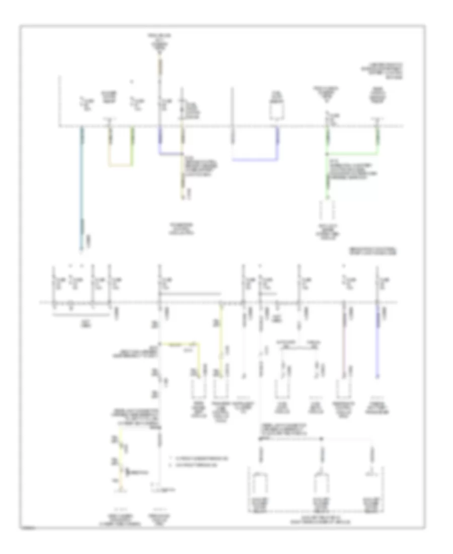
Power Distribution Wiring Diagram (5 of 5) for Ford Expedition 2012
List of elements for Power Distribution Wiring Diagram (5 of 5) for Ford Expedition 2012:
- (behind right kick panel) smart junction box (sjb)
- (center front of engine compartment) battery junction box (bjb)
- (not used)
- (rear light connector harness, in breakout to auxiliary relay box 2) s420
- (rear light connector harness, near breakout to left "c" pillar)
- (w/ rear view camera) s408
- Anti-lock brake system (abs) module
- Automatic a/c
- Auxiliary blower motor relay 1
- Auxiliary blower motor relay 2
- Auxiliary blower motor relay 3
- Auxiliary relay box 2 (right rear corner of vehicle)
- Blower motor relay
- C175b
- C210
- C2280b
- C2280d
- C2280e
- C228a
- C2357a
- C2371a
- C3054b
- C310a
- C314
- C4014a
- C411
- C438 (expedition)
- C465
- C919
- From fuse 53 (diagram 1 of 5) c
- From splice s117 (diagram 1 of 5)
- Fuel pump motor diode
- Fuel pump relay
- Fuse 10a
- Fuse 30a
- Fuse 5a
- Fuse 7.5a
- Hvac (datc) module
- Hvac (emtc) module
- Instrument cluster (ic)
- Manual a/c
- Parking aid module (pam)
- Passive anti-theft transceiver
- Powertrain control module (pcm)
- Rear heated seat module
- Rear window defrost relay
- Restraints control module (rcm)
- S119 (expedition: in battery junction box (bjb)) (navigator: on rear dash harness, near g201)
- S120 (engine control sensor harness, under battery junction box)
- S316 (body main harness, near breakout to g301)
- Tan
- Transfer case control module (tccm)
- Video camera (navigation w/ rear video camera)
- W/ front & rear parking aid
- W/o front parking aid