POWER DISTRIBUTION
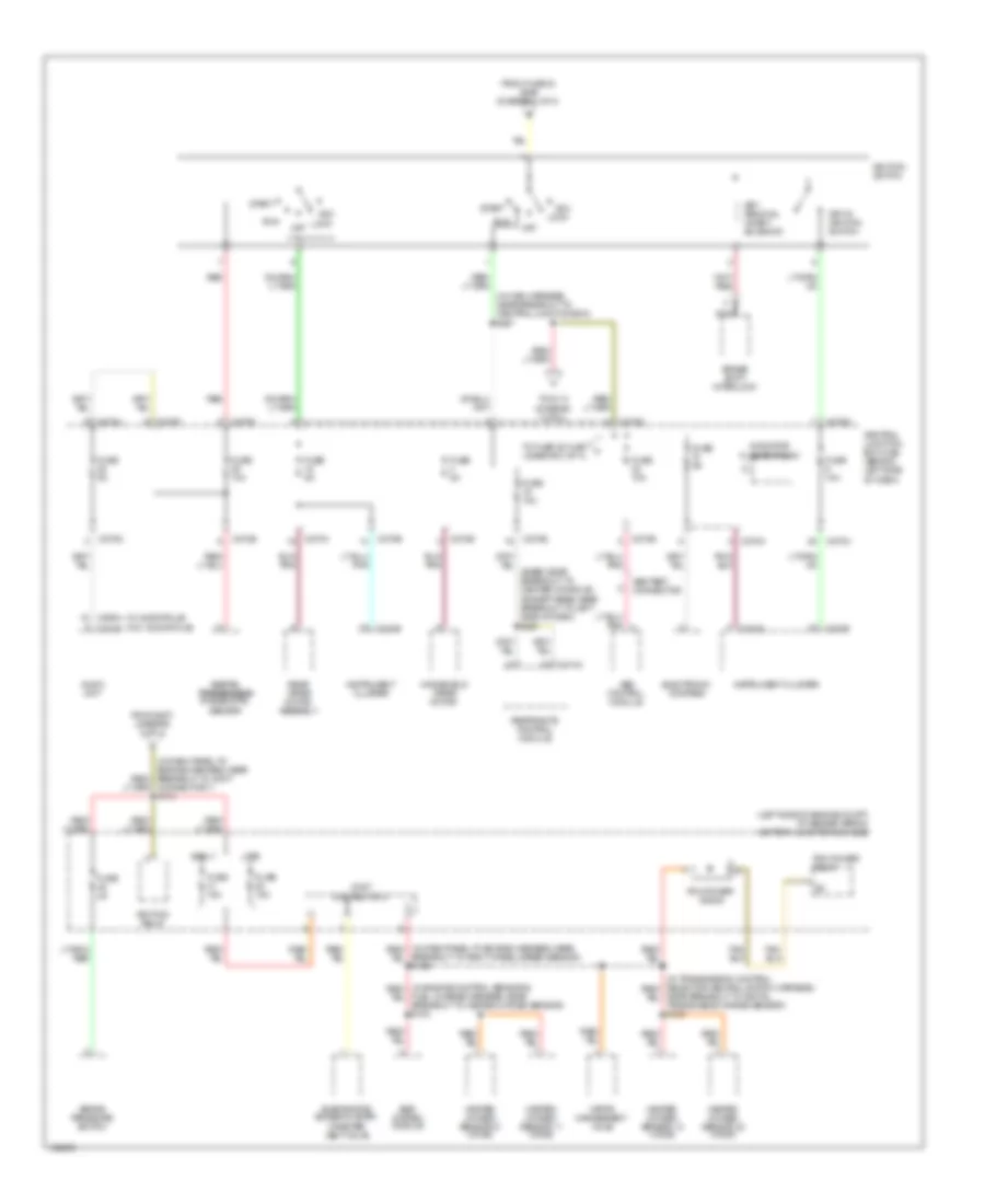
Power Distribution Wiring Diagram (1 of 4) for Ford Explorer 2004

List of elements for Power Distribution Wiring Diagram (1 of 4) for Ford Explorer 2004:
- (diagram 3 of 4)
- (in dash panel to engine harness, near breakout to right side of engine compt)
- (in window regulator jumper assembly, near breakout to c3134) s313
- (left side of engine compt, at fender apron) battery junction box (bjb)
- Abs control module
- Adjustable pedal switch
- Auxiliary a/c relay
- Auxiliary junction box (ajb)
- Battery
- Battery junction box (bjb) (left side of engine compartment, at fender apron)
- Battery junction box (bjb) (left side of engine compt, at fender apron)
- Blower motor relay
- C1035a
- C1035b
- C175b
- C205a
- C270c
- C3203e
- Central junction box (cjb) (behind left side of dash)
- Circuit breaker 30a
- Console 1 power point (in center console)
- Console 2 power point (in center console)
- Daytime running lamps (drl) module
- Engine compartment relay box (at right side of engine compartment)
- From b fuse 6 (bjb) (diagram 1 of 4)
- From fuse 8 (bjb) (diagram 1 of 4)
- Fuel pump relay
- Fuse 10a
- Fuse 15a
- Fuse 20a
- Fuse 30a
- Fuse 40a
- Fuse 50a
- Fuse 5a
- Fuse 60a
- G200 (at right ``a'' pillar)
- Generator
- Harness, near breakout to joint connector 1) s170
- Horn relay
- Ignition relay
- Left turn trailer tow relay
- Main light switch
- Nca
- Parking lamp trailer tow relay
- Pcm power relay
- Powertrain control module (pcm)
- Rear auxiliary junction box (ajb) (at right ``d" pillar)
- Rear window defrost relay
- Rear wiper motor assembly
- Red
- Regulator jumper assembly, near breakout to g401) s412
- Reversing lamp trailer tow relay
- Right power seat switch
- Right turn trailer tow relay
- S116
- S119
- S143 (at battery cable assembly, near breakout to battery junction box)
- S216
- Starter motor
- Starter relay
- Tan/ (in main harness, near breakout to central junction box) s259
- To accessory delay relay (cjb) (diagram 3 of 4)
- To fuse 10 (cjb)
- To fuse 11 (bjb) (diagram 1 of 4)
- To fuse 15 (bjb) (diagram 3 of 4)
- To fuse 16 (cjb) (diagram 4 of 4)
- To fuse 26 (bjb) (diagram 1 of 4)
- To fuse 5 (cjb) (diagram 3 of 4)
- To ignition switch (diagram 2 of 4)
- Trailer electronic brake control module
- Trailer tow battery charge relay
- Transfer case high to low relay
- Transfer case low to high relay
- Vehicle security module (vsm)
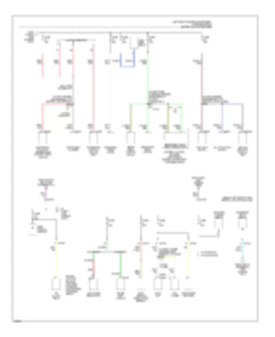
Power Distribution Wiring Diagram (2 of 4) for Ford Explorer 2004
List of elements for Power Distribution Wiring Diagram (2 of 4) for Ford Explorer 2004:
- (base: near breakout to center console) (except base: near breakout to left side of dash) s261
- (diagram 4 of 4)
- (in main harness, near breakout to central junction box) s207
- (left side of engine compt, at fender apron) battery junction box (bjb)
- (w/ audiophile)
- (w/o audiophile)
- Abs control module
- Abs test connector
- Acc
- Audio unit
- Brake pressure switch
- Brake shift interlock
- Breakout to right wheel speed sensor) s129
- C220a
- C220b
- C240b
- C270a
- C270b
- C270d
- C270e
- C270f
- C270g
- C270h
- C290a
- C310a
- Central junction box (cjb) (behind left side of dash)
- Connector 1) s113
- Digital digital transmission transmission range (dtr) sensor
- Early
- Egr system module
- Electronic compass
- Evaporative emission (evap) canister vent valve
- From fuse 23 (bjb) (diagram 1 of 4)
- From s207 (diagram 2 of 4)
- Fuel charge harness, near breakout to heated oxygen sensor) s103
- Fuse 10a
- Fuse 15a
- Fuse 2a
- Fuse 5a
- Heated oxygen sensor 11 (ho2s)
- Heated oxygen sensor 12 (ho2s)
- Heated oxygen sensor 21 (ho2s)
- Heated oxygen sensor 22 (ho2s)
- Ignition relay
- Ignition switch
- Indicator flasher relay
- Instrument cluster
- Joint connector 2
- Key in ignition switch
- Key removal inhibit solenoid
- Late
- Lock
- Nca
- Near breakout to digital transmission range sensor) s100
- Off
- Pcm power diode
- Pcm power relay
- Rear wiper motor assembly
- Red
- Restraints control module
- Run
- Start
- To fuse 25 (cjb) j
- To s113 (diagram 2 of 4)
- Vapor management valve
- Windshield wiper motor
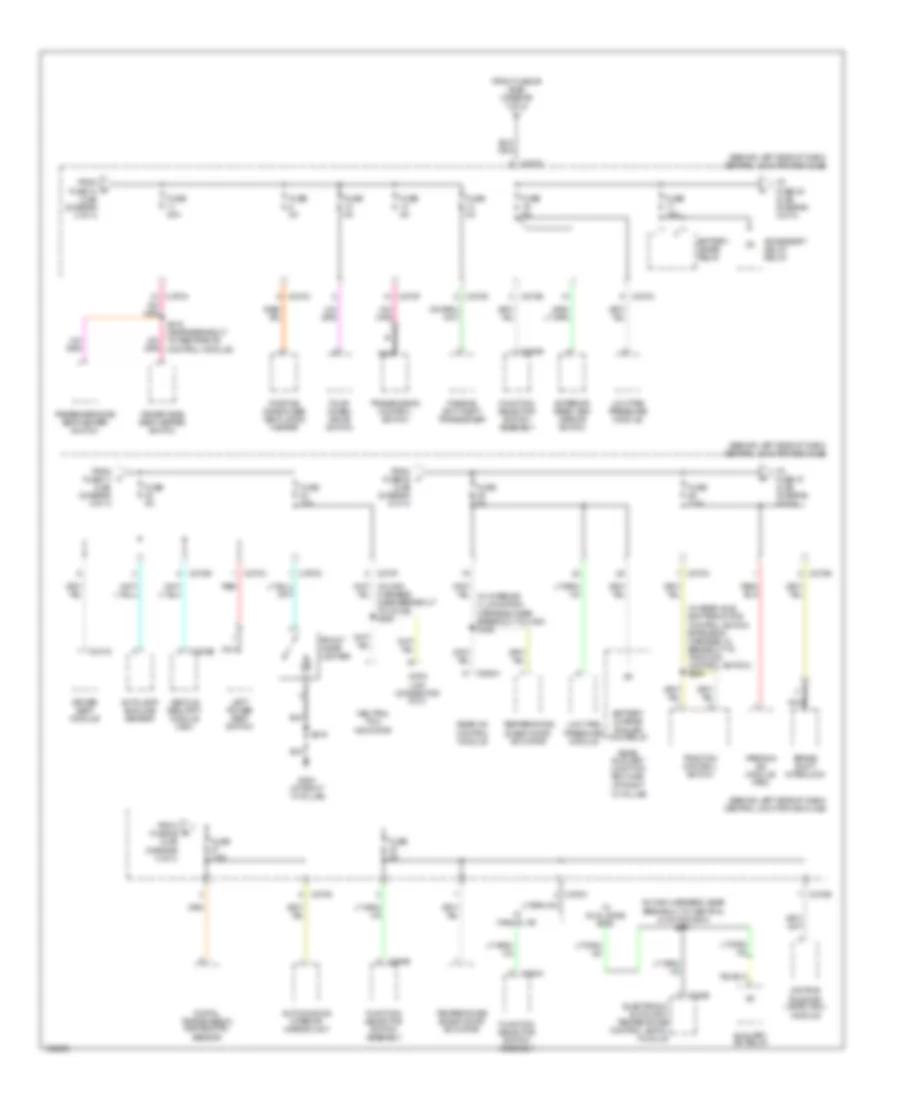
Power Distribution Wiring Diagram (3 of 4) for Ford Explorer 2004
List of elements for Power Distribution Wiring Diagram (3 of 4) for Ford Explorer 2004:
- (behind left side of dash) central junction box (cjb)
- (in dash panel to engine harness, near breakout to joint connector 1) s171
- (in main harness, near breakout to central junction box) s205
- (in main harness, near breakout to central junction box) s232
- (left side of engine compartment, at fender apron) battery junction box (bjb)
- A/c clutch relay
- Accessory delay relay
- Audio unit
- Battery junction box (bjb) (left side of engine compartment, at fender apron)
- Brake pedal position switch
- Brake pedal relay (early production)
- C175b
- C202c
- C205a
- C220a
- C228b
- C240b
- C270a
- C270b
- C270c
- C270d
- C270g
- C3203e
- C341e
- Driver seat module
- Dvd player
- Electronic automatic temperature control (eatc) module
- From circuit breaker 62 (bjb) (diagram 1 of 4)
- From fuse 1 (bjb) (diagram 1 of 4)
- From fuse 23 (bjb) (diagram 1 of 4)
- From ignition relay (bjb) (diagram 1 of 4)
- Fuse 10a
- Fuse 15a
- Fuse 20a
- Fuse 30a
- High beam relay
- Indicator flasher relay
- Instrument cluster
- Joint connector 1
- Left power seat switch
- Main light switch
- Multi-function switch
- Nca
- Powertrain control module (pcm)
- Rear window defrost
- Red
- Redundant pedal switch
- Roof opening panel motor assembly
- Subwoofer amplifier
- To fuse 11 (cjb) (diagram 4 of 4)
- Vehicle security module (vsm)
- W/ audiophile
- W/ dual zone eatc
- W/ dvd player
- W/ ivd
- W/ memory
- W/o audiophile
- W/o memory
- Windshield wiper motor
Power Distribution Wiring Diagram (4 of 4) for Ford Explorer 2004
List of elements for Power Distribution Wiring Diagram (4 of 4) for Ford Explorer 2004:
- (behind left side of dash) central junction box (cjb)
- (in main harness, near breakout to central junction box) s247
- (in rear axle shifter motor control switch extension harness, in breakout to traction control switch) s264
- Accessory delay relay
- Auto-dimming interior mirror unit
- Autolamp/ sunload sensor
- Auxiliary a/c relay
- Battery charge trailer tow relay
- Battery saver relay
- Brake shift interlock
- C228b
- C270a
- C270b
- C270c
- C270d
- C270e
- C270f
- C270g
- C270h
- C294a
- C294b
- C3203e
- C341g
- C938a
- Data link connector (dlc)
- Daytime running lamps (drl) module
- Digital transmission range (dtr) sensor
- Driver seat module
- Driver side seat heater switch
- Electronic automatic temperature control (eatc) module
- Exterior rear view mirror switch
- Four- wheel drive switch
- From fuse 10 (cjb) (diagram 3 of 4)
- From fuse 17 (cjb) (diagram 4 of 4)
- From fuse 22 (cjb) (diagram 2 of 4)
- From fuse 26 (cjb) (diagram 4 of 4)
- From fuse 29 (bjb) (diagram 1 of 4)
- Front cigar lighter
- Function selector switch assembly
- Fuse 15a
- Fuse 20a
- Fuse 5a
- Fuse 7.5a
- G200 (at right ``a" pillar)
- Harness, near breakout to c2126) s263
- Left power seat switch
- Low tire pressure module
- Nca
- Neutral tow indicator
- Parking aid module (pam)
- Passenger side seat heater switch
- Passive anti-theft transceiver
- Positive crankcase ventilation heater
- Rear a/c control module
- Rear auxiliary junction box (ajb) (at right ``d" pillar)
- Red
- S216
- Temperature blend door actuator
- To fuse 20 (cjb) (diagram 4 of 4)
- To fuse 27 (cjb) (diagram 4 of 4)
- Traction control switch
- Transmission control switch
- Vehicle security module (vsm)
- W/ dual zone eatc
- W/ manual a/c