POWER DISTRIBUTION
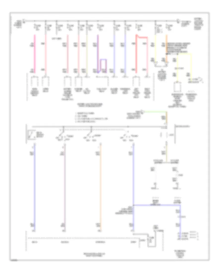
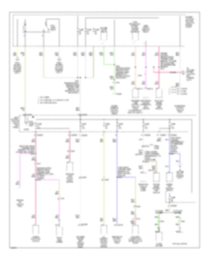
Power Distribution Wiring Diagram (1 of 7) for Ford F-150 Platinum 2014

List of elements for Power Distribution Wiring Diagram (1 of 7) for Ford F-150 Platinum 2014:
- (alternator rectifier system wiring harness, in breakout to fusible link e) s143
- (engine control sensor wiring harness, in breakout red
- (engine control sensor wiring harness, in breakout to fusible link a) s109
- (front of engine compt) battery junction box (bjb)
- (main wiring harness, near breakout to g203) (w/ adjustable pedal/ tilt/telescope column) s212
- 6.2l
- Anti-lock brake system (abs) module
- Audio control module (acm)
- Automatic a/c
- Base
- Battery
- Body control module (right kick panel)
- C1035a
- C1035b
- C1463a
- C1617a
- C1617b
- C192
- C2108
- C211
- C213
- C215
- C2280a
- C2280g
- C228a
- C2357
- C2371b
- C2414b
- C264
- C290a
- C294a
- C312
- C3313b
- Crew chief
- Data link connector (dlc)
- Eatc hvac module
- Emtc hvac module
- Except 6.2l
- Except base
- From battery junction box (bjb) (diagram 1 of 7)
- Front cigar lighter
- Fuse (except 6.2l) 10a
- Fuse 10a
- Fuse 15a
- Fuse 20a
- Fuse 30a
- Fuse 40a
- Fuse 60a
- G203 (left side of dash)
- Generator
- Generator current sensor
- High current battery junction box (right front corner of engine compt)
- Inline fuse (center of dash)
- Instrument panel cluster (ipc)
- Instrument panel power point
- Integrated wheel end (iwe) solenoid (w/ electronic shift on the fly)
- Left headlamp (w/ hid)
- Manual a/c
- Mega fuse 125a
- Mega fuse 250a
- Nca
- Passenger side front seat control switch (w/ 10-way power seat)
- Power running board (prb) module
- Power steering control module
- Premium audio
- Red
- Right headlamp (w/ hid)
- S142 (alternator rectifier system wiring harness, in breakout to fusible link e)
- S144 (alternator rectifier system wiring harness, in breakout to fusible link e)
- S272 (crew chief) (t-box jumper wiring harness, near breakout to c2108)
- Starter motor
- Steering column control module (sccm) (w/ adjustable pedal/ tilt/telescope column)
- Telematics module (crew chief)
- To dc/ac inverter module (diagram 3 of 7)
- To fuse 27 (diagram 3 of 7)
- To fuse 32 (diagram 2 of 7)
- To fusible link a) s110
- To ignition switch (diagram 2 of 7)
- To splice s110 (diagram 1 of 7)
- Trailer brake control (tbc) module
- Transfer case control module (tccm) (w/ electronic shift on the fly)
- W/ column shifter
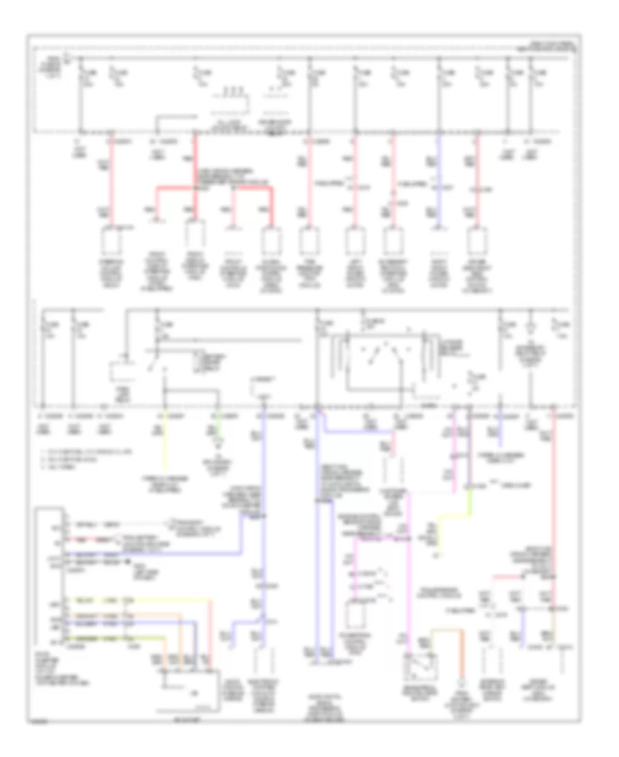
Power Distribution Wiring Diagram (2 of 7) for Ford F-150 Platinum 2014
List of elements for Power Distribution Wiring Diagram (2 of 7) for Ford F-150 Platinum 2014:
- (not used)
- 3.5l turbo
- 3.7l flex fuel, 3.7l cng & 3.7l lpg
- 5.0l flex fuel & 6.2l
- A/c clutch relay
- Acc
- Acc/run
- Battery charge trailer tow relay (7-pin trailer tow)
- Battery junction box (bjb) (front of engine compt)
- Blower motor relay
- Body control module (right kick panel)
- Brake shift interlock
- C1381b
- C1551b
- C1581
- C175b
- C214
- C2280b
- C329
- Evaporative emission (evap) canister vent solenoid (except 3.5l turbo)
- Except 3.5l turbo
- Floor shifter
- From e body control module (bcm) (diagram 1 of 7)
- From fuse 65 (diagram 1 of 7)
- Fuel pump relay
- Fuse 10a
- Fuse 15a
- Fuse 20a
- Fuse 30a
- Fuse 40a
- Fuse 40a 50a
- Fuse 5a
- Ignition switch
- Key in
- Key in ignition switch
- Left turn trailer tow relay
- Lock
- Micro
- Nca
- Off
- Powertrain control module (pcm)
- Rear window defrost relay
- Red
- Reversing lamp relay
- Right turn trailer tow relay
- Run
- S241 (main wiring harness, near breakout to c213)
- Start
- Start/run
- Starter relay
- To battery junction box (bjb) (diagram 7 of 7)
- To fuse 18 (diagram 5 of 7)
- W/ column shifter
- W/ floor shifter
- Wiper relay
- Wiring harness, near breakout to mass air flow/intake air temperature sensor) s101
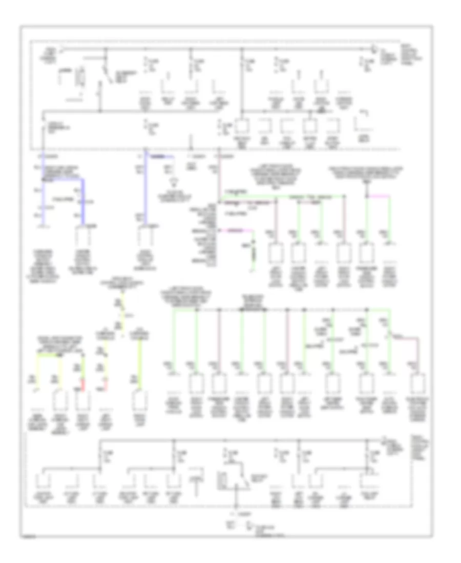
Power Distribution Wiring Diagram (3 of 7) for Ford F-150 Platinum 2014
List of elements for Power Distribution Wiring Diagram (3 of 7) for Ford F-150 Platinum 2014:
- (body main wiring harness, near breakout to audio digital signal processing module) s324
- (body main wiring harness, near breakout to c311) (w/ memory) s354
- (engine control sensor wiring harness, near breakout to c110)
- (main wiring harness, near breakout to dc/ac inverter module) s244
- (main wiring harness, near breakout to passenger air bag module) s220
- (not used)
- (right kick panel) body control module
- (taped in harness near c127)
- (taped in harness near c127) (if equipped)
- 3.5l turbo
- 3.7l flex fuel, 3.7l cng & 3.7l lpg
- 5.0l flex fuel & 6.2l
- Ac outlet
- Ac-a
- Ac-b
- Acc
- Accessory protocol interface module (apim) (w/ sync)
- All lock/ unlock relay
- Audio digital signal processing (dsp) module (w/ sony sound)
- Audio- dimming interior mirror
- Battery saver relay
- Brake pedal position (bpp) switch
- C1208
- C1381b
- C1551b
- C175b
- C214
- C219
- C2280a
- C2280b
- C2280d
- C2280e
- C2280f
- C2293a
- C2293b
- C237
- C238
- C2414a
- C248
- C300
- C314
- C3154c
- C329
- C341b
- C341c
- Cbp38
- Crew chief
- Customer access (w/o sony sound)
- Dc/ac inverter module (w/ 110v power inverter) (top center of dash)
- Driver door unlock relay
- Driver seat module (dsm) (w/ memory)
- Driver side front seat control switch (w/ memory)
- Electronic compass (w/o auto- dimming interior mirror)
- Exterior rear view mirror switch
- From battery junction box (bjb) (diagram 1 of 7)
- From battery junction box (diagram 5 of 7)
- From body control module (diagram 4 of 7)
- From fuse 46 (diagram 1 of 7)
- Front control display interface module (fcdim) (if equipped)
- Front controls interface module (fcim)
- Front display interface module (fdim)
- Fuse 10a
- Fuse 15a
- Fuse 20a
- Fuse 25 15a
- Fuse 30a
- Fuse 5a
- Fuse 7.5a
- G203 (left side of dash)
- Gd138
- Global positioning system module (gpsm) (w/ sync)
- Gnd
- Hya01
- Hya02
- If equipped
- Led+
- Led-
- Left front power window motor
- Liftgate release relay
- Lin 01
- Lya03
- Micro
- Park lamp relay
- Powertrain control module (pcm)
- Red
- Right front power window motor
- Rya03
- S112
- Sbb33
- Steering column control module (sccm)
- Tire pressure monitor (tpm) module
- To accessory delay relay (diagram 4 of 7)
- To splice s901 (diagram 4 of 7)
- Trailer brake control module
- Vdn01
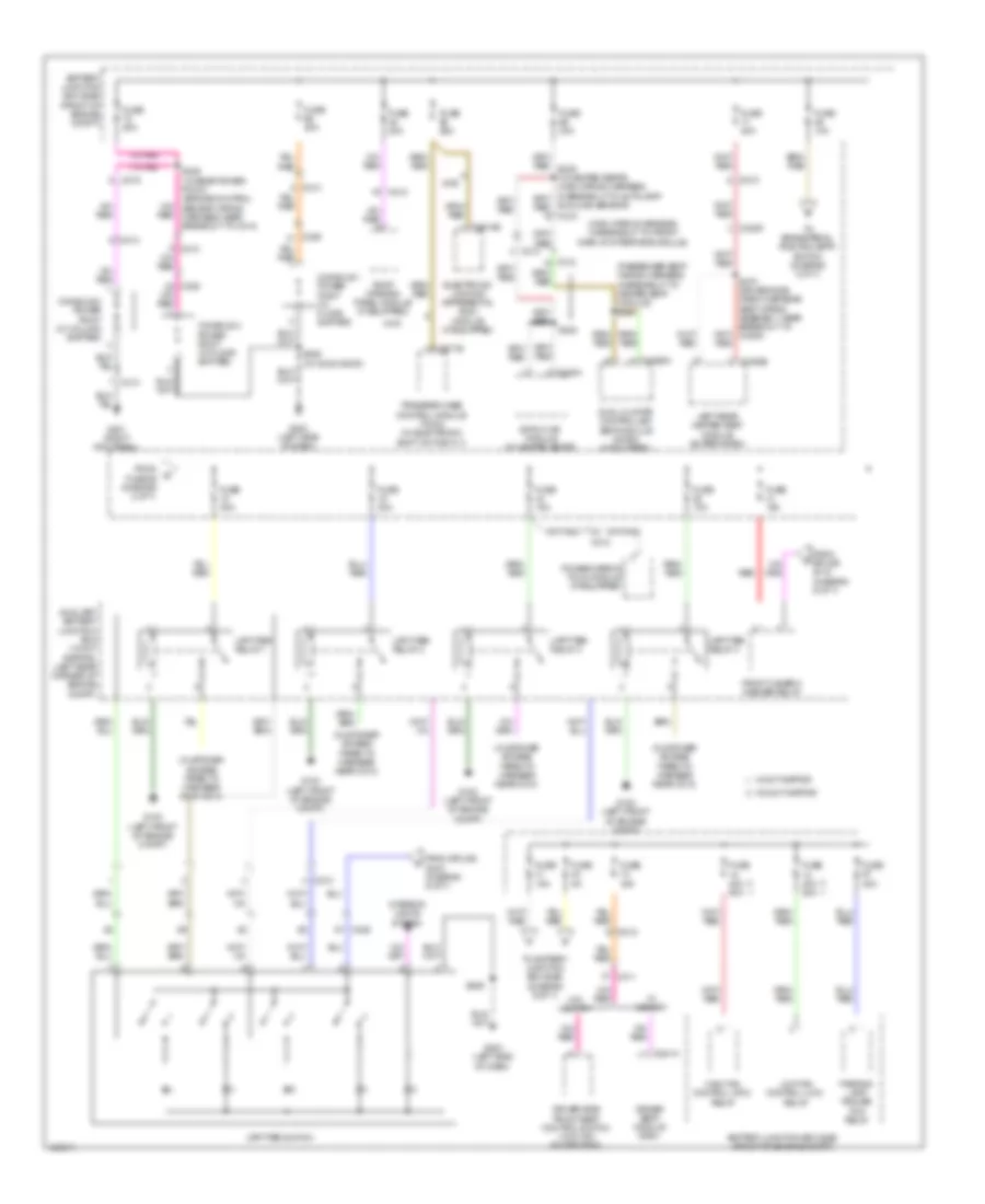
Power Distribution Wiring Diagram (4 of 7) for Ford F-150 Platinum 2014
List of elements for Power Distribution Wiring Diagram (4 of 7) for Ford F-150 Platinum 2014:
- (dome lamp connector wiring harness, near breakout to left left vanity mirror lamp) s901
- (left front door window regulator wiring harness, near breakout to driver front door side impact sensor) s504
- (left front door window regulator wiring harness, near breakout to exterior rear view mirror switch)
- (not used)
- (right front door window regulator wiring harness, near breakout to right front door lock switch) s605
- 3rd row seat (fet)
- Accessory delay relay
- Audio control module (acm) (base audio)
- Auto- dimming interior mirror
- Back- lighting led (fet)
- Body control module (right kick panel)
- Bsi (fet)
- C219
- C2280a
- C2280b
- C2280d
- C2280f
- C237
- C290a
- C314
- C315
- C316
- C327
- C535b
- Circuit breaker 48 30a
- Electronic compass (w/o auto- dimming interior mirror)
- Fog lamp relay
- From body control module (bcm) (diagram 3 of 7)
- From fuse 22 (diagram 4 of 7)
- From fuse 7 (diagram 3 of 7)
- Front dome lamp
- Front interior/ map lamps assembly
- Fuse 10a
- Fuse 15a
- Fuse 20a
- Horn relay
- If equipped
- Interior lighting (fet)
- Keypad illum (fet)
- Left front door lock switch
- Left front power window motor
- Left high beam (fet)
- Left low beam (fet)
- Left rear heated seat switch
- Left vanity mirror lamp
- Lf turn lamp (fet)
- Lh corner lamp (fet)
- Lr stop/ turn lamp (fet)
- Lr turn lamp (fet)
- Master window control switch (regular cab)
- Master window control switch (super crew & super cab)
- Micro
- Overhead console switch assembly (super crew, super cab & w/ power sliding rear window)
- Passenger side window control switch
- Pcm wake up (fet)
- Puddle lamp (fet)
- Rear interior/ map lamps assembly
- Red
- Rev lp (fet)
- Rf turn lamp (fet)
- Rh corner lamp (fet)
- Right front door lock switch
- Right front power window motor
- Right high beam (fet)
- Right low beam (fet)
- Right rear heated seat switch
- Right vanity mirror lamp
- Roof opening panel module
- Rr stop/ turn lamp (fet)
- Rr turn lamp (fet)
- Run/acc relay
- S308 (regular cab: body main wiring harness, near breakout to c312) (super cab: body main wiring harness, near breakout to c313)
- Start button (fet)
- Stop/ chmsl (fet)
- Super crew
- Telescopic exterior rearview mirror switch
- To dc/ac inverter module (diagram 3 of 7)
- To fuse 47 (diagram 4 of 7)
- To splice s157 (diagram 7 of 7)
- W/ overhead console
- W/o overhead console
- White led (fet)
Power Distribution Wiring Diagram (5 of 7) for Ford F-150 Platinum 2014
List of elements for Power Distribution Wiring Diagram (5 of 7) for Ford F-150 Platinum 2014:
- (customer access taped to harness near c214)
- (main wiring harness, in breakout to front display interface module)
- (passenger seat wiring harness, in breakout to heated seat module) s341
- 2wd
- 4wd
- Auxiliary battery junction box (w/ svt raptor) (left rear corner of engine compt)
- Battery junction box (bjb) (front of engine compt)
- C210
- C212
- C213
- C215
- C228a
- C2371b
- C2613b
- C311
- C312
- C313
- C3162b
- C3205
- C3265a f
- C329
- C341a
- Console 1 power point (w/ floor shifter)
- Console 2 power point (w/ column shifter)
- Console 2 power point (w/ floor shifter)
- Driver seat module (dsm)
- Driver side front seat control switch (w/ 6-way power seat)
- Dual climate controlled seat module (dcsm) (if equipped)
- Eatc hvac module (w/ heated seats)
- Electronic locking differential (eld) module (if equipped)
- From fuse 26 (diagram 2 of 7)
- From splice s118 (diagram 6 of 7)
- From splice s243 (diagram 6 of 7)
- Front camera washer relay
- Fuse 10a
- Fuse 15a
- Fuse 20a
- Fuse 25a
- Fuse 30a
- Fuse 40a 50a
- Fuse 5a
- G102 (left front of engine compt)
- G201 (right kick panel)
- G203 (left side of dash)
- High fan control (hfc) relay
- Interior lights system
- Left rear heated seat module (super crew)
- Low fan control (lfc) relay
- Parking lamp trailer tow relay
- Power mirror fold module (if equipped)
- Red
- Roof opening panel module (if equipped)
- S222
- S246 (w/ rear power point) (engine control sensor wiring harness, near breakout to c214)
- S329
- S329 (w/ moon roof)
- S370 (driver side crew cab rear seat wiring assembly, near breakout to c3205)
- Sunload sensor)
- To battery junction box (bjb) (diagram 6 of 7)
- To brake pedal position (bpp) switch (diagram 3 of 7)
- Transfer case control module (tccm) (w/ electronic shift on the fly)
- Upfitter relay 1
- Upfitter relay 2
- Upfitter relay 3
- Upfitter relay 4
- Upfitter switch
- W/ memory
- W/ svt raptor
- W/o memory
- W/o svt raptor
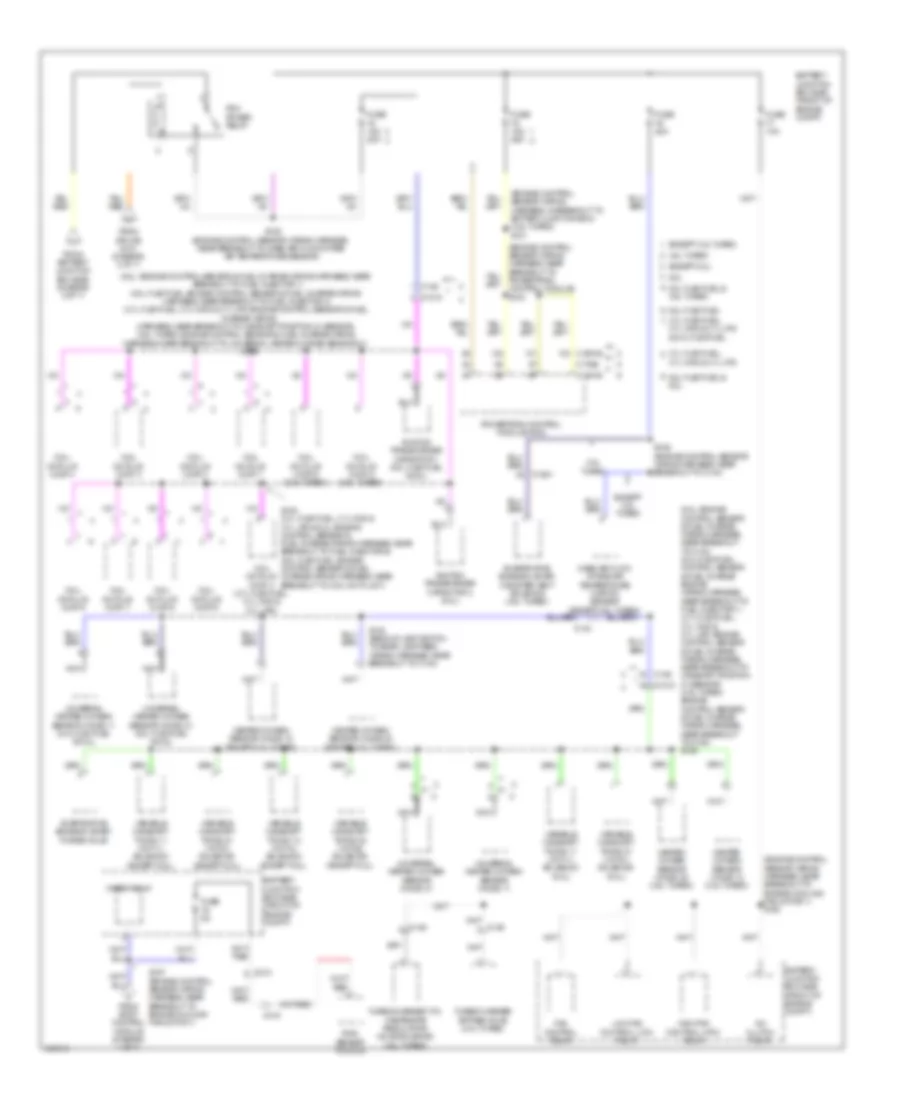
Power Distribution Wiring Diagram (6 of 7) for Ford F-150 Platinum 2014
List of elements for Power Distribution Wiring Diagram (6 of 7) for Ford F-150 Platinum 2014:
- (7-pin trailer tow) battery charge trailer tow relay
- (body main wiring harness, near breakout to g202) (w/ rear view camera) s203
- (engine control sensor wiring harness, near breakout to mass air flow/intake air temperature sensor) s118
- (main wiring harness, near breakout to body control module) s242
- (main wiring harness, near breakout to passenger air bag module) (w/ svt raptor) s243
- (not used)
- (t-box jumper wiring harness, near breakout to c2108) (crew chief) s274
- (w/ front camera) s119
- 2wd
- 3.5l turbo
- 3.7l flex fuel, 3.7l cng & 3.7l lpg
- 5.0l flex fuel & 6.2l
- Anti-lock brake system (abs) module
- Battery junction box (bjb) (front of engine compt)
- Blower motor relay
- Body control module (right kick panel)
- C1381b
- C139
- C145
- C1463b
- C1551b
- C175b
- C2108
- C212
- C2280b
- C2280d
- C2280e
- C2280f
- C2371a
- C238
- C2613a
- C264
- C310a
- C312
- C3162b
- C3205
- C329
- Camera switching module
- Crew chief
- Electronic locking differental (eld) module
- Floor shifter
- From battery junction box (bjb) (diagram 5 of 7)
- Front video camera
- Fuse 10a
- Fuse 5a
- Fuse 7.5a
- Hazard/ pad/ traction switch
- Hill descent control switch (w/ svt raptor)
- Left rear heated seat module (super crew)
- Micro
- Nca
- Occupant classification system module (ocsm)
- Off-road mode switch (w/ svt raptor)
- Parking aid module (pam)
- Power steering control module (pscm)
- Powertrain control module (pcm)
- Rear window defrost relay
- Restraints control module (rcm)
- Run/ start (fet)
- Run/ start relay
- S156 (engine control sensor wiring harness, near breakout to engine cooling fan motor 1)
- S161 (engine control sensor wiring harness, near breakout to engine cooling fan motor 1)
- Telematics module (crew chief)
- To auxiliary battery junction box (diagram 5 of 7)
- To upfitter switch (diagram 5 of 7)
- Tow haul switch
- Trailer brake control (tbc) module
- Transfer case control module (tccm) (w/ electronic shift on the fly)
- W/ column shifter
- W/ floor shifter
Power Distribution Wiring Diagram (7 of 7) for Ford F-150 Platinum 2014
List of elements for Power Distribution Wiring Diagram (7 of 7) for Ford F-150 Platinum 2014:
- (6.2l: engine control sensor & fuel charge wiring harness, near breakout to c133) (5.0l flex fuel: control sensor & fuel charge engine wiring harness, near breakout to fuel injector 1) (3.7l flex fuel, 3.7l cng & 3.7l lpg: engine control sensor & fuel charge wiring harness, near breakout to camshaft position 21 sensor) (3.5l turbo: engine control sensor & fuel charge wiring harness, near breakout to c180) s136
- (6.2l: engine control sensor & fuel charge wiring harness, near breakout to fuel injector 1) (5.0l flex fuel: engine control sensor & fuel charge wiring harness, near breakout to fuel injector 4) (3.7l flex fuel, 3.7l cng & 3.7l lpg: engine control sensor & fuel
- (engine control sensor wiring harness, in breakout to battery junction box) (3.5l turbo) s121
- (engine control sensor wiring harness, near breakout to engine cooling fan motor 1) s105
- (engine control sensor wiring harness, near breakout to powertrain control module) s103
- 3.5l turbo
- 3.7l cng & 3.7l lpg
- 3.7l cng & 3.7l lpg & 5.0l flex fuel
- 3.7l flex fuel,
- 5.0l flex fuel
- 5.0l flex fuel & 3.5l turbo
- 5.0l flex fuel & 6.2l
- 6.2l
- A/c clutch relay
- Battery junction box (bjb) (front of engine compt)
- C1010
- C136
- C1381b
- C140
- C146
- C1551b
- C1581
- C175b
- C212
- C315
- Charge wiring harness, near breakout to camshaft position 21 sensor) (3.5l turbo: engine control sensor & fuel charge wiring harness, near breakout to universal heated oxygen sensor 21)
- Coil on plug (cop) 1
- Coil on plug (cop) 2
- Coil on plug (cop) 3
- Coil on plug (cop) 4
- Coil on plug (cop) 4 (3.7l flex fuel, 3.7l cng & 3.7l lpg)
- Coil on plug (cop) 5
- Coil on plug (cop) 5 (3.5l turbo)
- Coil on plug (cop) 6
- Coil on plug (cop) 6 (3.5l turbo)
- Coil on plug (cop) 7
- Coil on plug (cop) 8
- Evaporative emission (evap) canister vent solenoid (3.5l turbo)
- Evaporative emission (evap) purge valve
- Except 3.5l turbo
- Except 6.2l
- Fan control relay
- From battery junction box (bjb) (diagram 2 of 7)
- From body control module (diagram 4 of 7)
- From splice s101 (diagram 2 of 7)
- Fuse 10a
- Fuse 15a 20a
- Fuse 15a 25a
- Fuse 20a
- Fuse 5a
- Heated oxygen sensor (ho2s) 12 (3.5l turbo)
- Heated oxygen sensor (ho2s) 12 (except 3.5l turbo)
- Heated oxygen sensor (ho2s) 22 (3.5l turbo)
- Heated oxygen sensor (ho2s) 22 (except 3.5l turbo)
- High fan control (hfc) relay
- Ignition transformer capacitor 1 (5.0l flex fuel & 6.2l)
- Ignition transformer capacitor 2 (6.2l)
- Low fan control (lfc) relay
- Mass air flow/ intake air temperature (maf/iat) sensor (except 3.5l turbo)
- Nca
- Pcm power relay
- Powertrain control module (pcm)
- Rain sensor module
- S125 (engine control sensor wiring harness, near breakout to mass air flow/intake air temperature sensor)
- S129 (engine control sensor wiring harness, near breakout to c144)
- S135 (3.7l flex fuel, 3.7l cng & 3.7l lpg & 6.2l: engine control sensor & fuel charge wiring harness, near breakout to fuel injector 6) (5.0l flex fuel: engine control sensor & fuel charge wiring harness, near breakout to coil on plug 7)
- S139
- S148 (backup lamp switch to rear lamp feed wiring harness, near breakout to c140)
- S157 (engine control sensor wiring harness, near breakout to engine cooling fan motor 1)
- Turbocharger (tc) wastegate regulating valve solenoid (3.5l turbo)
- Turbocharger bypass valve (3.5l turbo)
- Universal heated oxygen sensor (ho2s) 11
- Universal heated oxygen sensor (ho2s) 11 (5.0l flex fuel & 6.2l)
- Universal heated oxygen sensor (ho2s) 21
- Universal heated oxygen sensor (ho2s) 21 (5.0l flex fuel & 6.2l)
- Variable camshaft timing 11 (vct11) solenoid (6.2l)
- Variable camshaft timing 11 (vct11) solenoid (except 6.2l)
- Variable camshaft timing 12 (vct12) solenoid (except 6.2l)
- Variable camshaft timing 21 (vct21) solenoid (6.2l)
- Variable camshaft timing 21 (vct21) solenoid (except 6.2l)
- Variable camshaft timing 22 (vct22) solenoid (except 6.2l)
- Wiper relay