POWER DISTRIBUTION
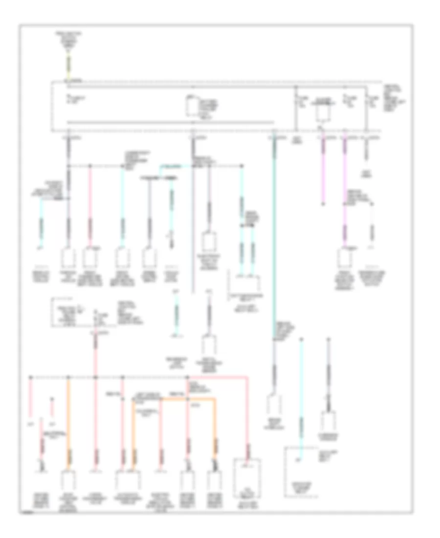
Power Distribution Wiring Diagram (1 of 4) for Ford F450 Super Duty 2002

List of elements for Power Distribution Wiring Diagram (1 of 4) for Ford F450 Super Duty 2002:
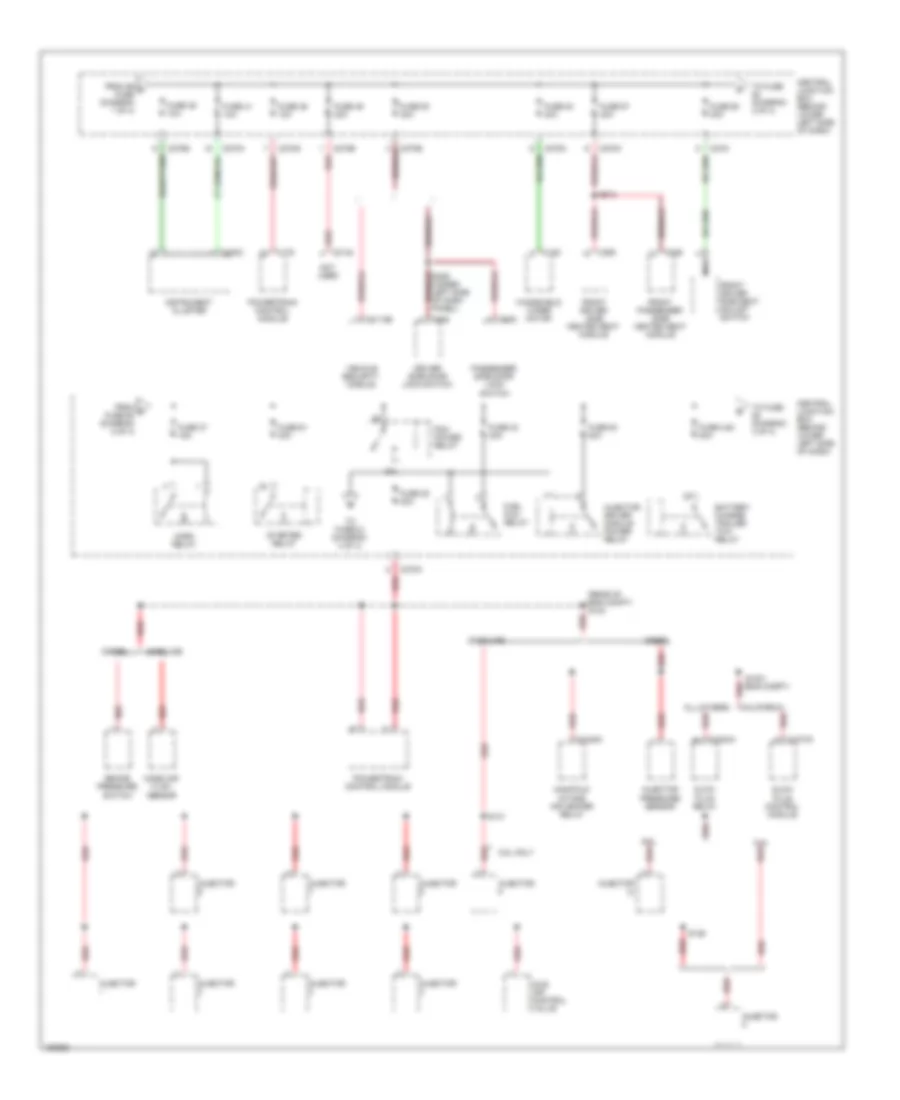
Power Distribution Wiring Diagram (2 of 4) for Ford F450 Super Duty 2002
List of elements for Power Distribution Wiring Diagram (2 of 4) for Ford F450 Super Duty 2002:
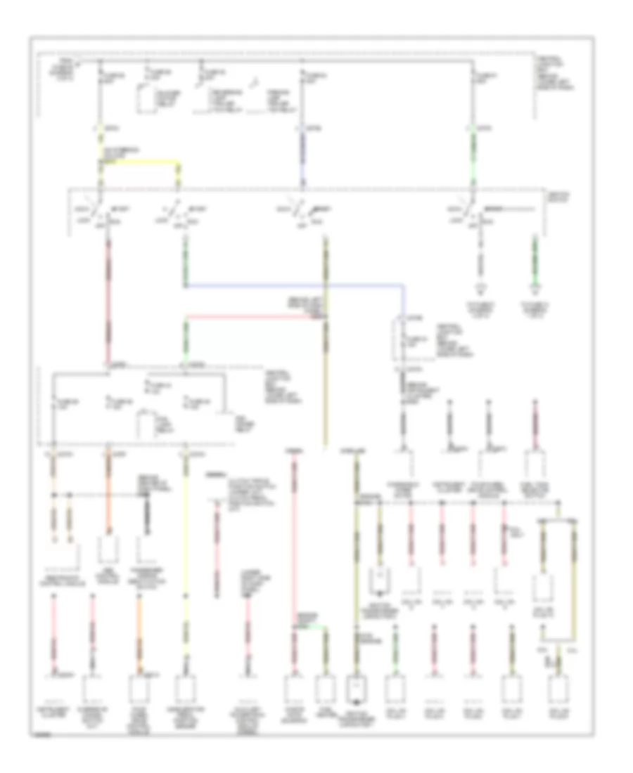
Power Distribution Wiring Diagram (3 of 4) for Ford F450 Super Duty 2002
List of elements for Power Distribution Wiring Diagram (3 of 4) for Ford F450 Super Duty 2002:
Power Distribution Wiring Diagram (4 of 4) for Ford F450 Super Duty 2002
List of elements for Power Distribution Wiring Diagram (4 of 4) for Ford F450 Super Duty 2002: