POWER DISTRIBUTION
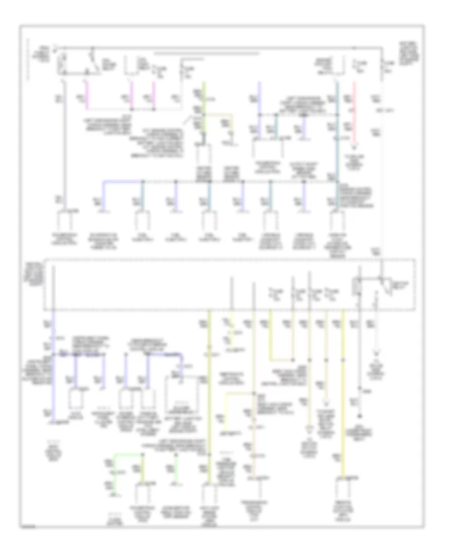
Power Distribution Wiring Diagram (1 of 5) for Ford Fiesta SE 2011

List of elements for Power Distribution Wiring Diagram (1 of 5) for Ford Fiesta SE 2011:
- (engine control wiring harness, in breakout to transmission control module) s100
- (not used)
- A/c clutch relay
- A/t
- Anti-lock brake system (abs) module
- Battery
- Battery junction box (bjb) (left side of engine compt)
- Blower motor relay
- Body control module (bcm)
- C1100a
- C133
- C1617a
- C1617b
- C1617c
- C1750a
- C175b
- C210
- C211
- C2280a
- C2368a
- C504a
- Coil pack relay
- Daytime running lamps (drl) relay
- Engine cooling fan relay
- Exterior rear view mirror switch (early production)
- From fuse 11 (diagram 1 of 5)
- Fuse 10a
- Fuse 15a
- Fuse 20a
- Fuse 30a
- Fuse 40a
- Fuse 50a
- Fuse 7.5a
- Generator
- High beam relay
- High current battery junction box (bjb) (at battery)
- Low beam relay
- M/t
- Master window control switch (early production)
- Mega fuse 1 450a
- Mega fuse 2 60a
- Mega fuse 3 200a
- Mega fuse 4 70a
- Mega fuse 5 50a
- Natural vacuum leak detection module (nvldm)
- Power steering control module (pscm)
- Powertrain control module (pcm)
- Red
- Starter inhibit relay
- Starter motor
- To fuse 4 (diagram 1 of 5)
- To pcm power relay (diagram 2 of 5)
- Transmission control module (tcm) (a/t)
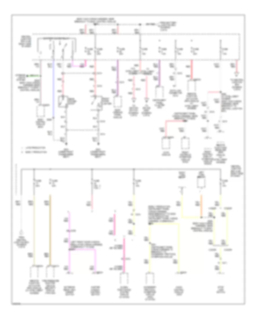
Power Distribution Wiring Diagram (2 of 5) for Ford Fiesta SE 2011
List of elements for Power Distribution Wiring Diagram (2 of 5) for Ford Fiesta SE 2011:
- (left side engine compt wiring harness, near breakout to battery junction box) s118
- (left side engine compt wiring harness, near breakout to battery junction box) s122
- (m/t: engine control wiring harness, in breakout to high current battery junction box) (a/t: engine control wiring harness, in breakout to ignition coil)
- (near breakout to power steering control module) s213
- Accelerator pedal position (app) sensor
- Anti-lock brake system (abs) module
- Battery junction box (bjb) (left side of engine compt)
- Blower motor relay
- Body control module (bcm)
- C133
- C1750a
- C175b
- C210
- C211
- C212
- C2280b
- C228a
- C2368b
- C310a
- C3503b
- C4321a
- Central junction box (cjb) (left side of engine compt)
- Coil pack relay
- Engine cooling fan relay
- Evaporative emission (evap) canister purge valve
- Floor shifter
- From fuse 27 (diagram 1 of 5)
- Fuel injector 1
- Fuel injector 2
- Fuel injector 3
- Fuel injector 4
- Fuse 10a
- Fuse 15a
- Fuse 60a
- Fuse 7.5a
- G301 (under front passenger's seat)
- Heated oxygen sensor (ho2s) 11
- Heated oxygen sensor (ho2s) 12
- Hvac module
- Ignition relay
- Instrument panel cluster (ipc)
- Mass air flow/ intake air temperature (maf/iat) sensor
- Nca
- Output shaft speed (oss) sensor (m/t w/o abs)
- Passive anti-theft transceiver (w/o intelligent access)
- Pcm power relay
- Power steering control module (pscm)
- Powertrain control module (pcm)
- Remote function actuator (rfa) module
- Restraints control module (rcm)
- S102 (engine control wiring harness, near breakout to camshaft position sensor)
- S103
- S116 (left side engine compt wiring harness, near breakout to battery junction box)
- S228
- S239 (instrument panel wiring harness, near breakout to blower motor resistor)
- S256
- S257 (a/t) (body main wiring harness, near breakout to c214)
- S259 (body main wiring harness, near breakout to central junction box)
- Tire pressure monitor/ vehicle security module (tpm/vsm)
- To ignition switch (diagram 4 of 5)
- To smart keyless entry ignition relay (diagram 4 of 5)
- To splice s252 (diagram 3 of 5)
- To splice s255 (diagram 5 of 5)
- Transmission control module (tcm) (a/t)
- Variable camshaft timing (vct) solenoid 11
- Variable camshaft timing (vct) solenoid 12
Power Distribution Wiring Diagram (3 of 5) for Ford Fiesta SE 2011
List of elements for Power Distribution Wiring Diagram (3 of 5) for Ford Fiesta SE 2011:
- (body main wiring harness, near breakout to body control module) s252
- (body main wiring harness, near breakout to central junction box)
- (early production: instrument panel wiring harness, near breakout to g202) (late production: instrument panel wiring harness, in breakout) s226
- (instrument panel wiring harness, near breakout to g202) s225
- 4 door
- 5 door
- Accessory protocol interface module (apim) (w/ sync)
- Audio control module (acm)
- Battery saver relay
- Body control module (bcm)
- C211
- C212
- C213
- C2280c
- C228a
- C240a
- C314
- C315
- C339 a8
- C3503a
- C4321a
- C504a
- Central junction box (cjb) (right side of dash)
- Data link connector (dlc)
- Early production
- Exterior rear view mirror switch
- From battery junction box c (diagram 2 of 5)
- From central junction box (diagram 3 of 5)
- Front cigar lighter
- Front control/ display interface module (fcdim)
- Front controls interface module (fcim)
- Fuse 10a
- Fuse 15a
- Fuse 15a 7.5a
- Fuse 20a
- Fuse 7.5a
- G301 (under front passenger's seat)
- Global positioning system module (w/ sync)
- Hvac module
- Instrument panel cluster (ipc)
- Interior lights system
- Late production
- Left turn relay
- Master window control switch
- Rear power point
- Red
- Remote function actuator (rfa) module (w/ intelligent access)
- Remote functions receiver (rfr) module (w/ intelligent access)
- Right turn relay
- Roof opening panel module
- S201 (instrument panel wiring harness, in breakout to accessory protocol interface module)
- S248 (body main wiring harness near breakout to body control module)
- S250 (body main wiring harness, near breakout to body control module)
- S256
- Stop lamp switch
- Tire pressure monitor/ vehicle security module (tpm/vsm)
- To central junction box (diagram 3 of 5)
- To ignition switch (diagram 4 of 5)
- To splice s253 (diagram 4 of 5)
- W/ intelligent access
- W/o intelligent access
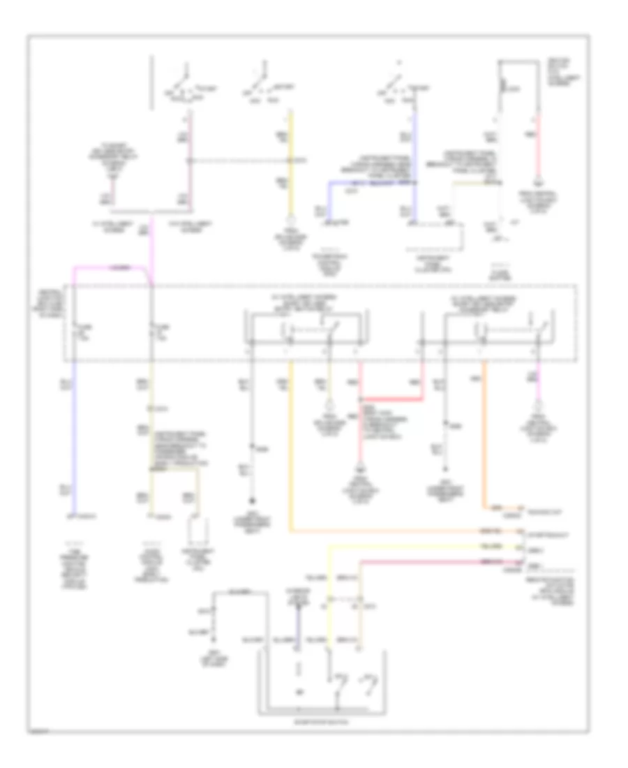
Power Distribution Wiring Diagram (4 of 5) for Ford Fiesta SE 2011
List of elements for Power Distribution Wiring Diagram (4 of 5) for Ford Fiesta SE 2011:
- (instrument panel wiring harness, in breakout to instrument panel cluster) (a/t) s219
- (instrument panel wiring harness, near breakout to instrument panel cluster) s230
- (w/ intelligent access) smart keyless entry accessory relay
- (w/ intelligent access) smart keyless entry ignition relay
- A/t
- Acc
- Audio control module (acm) (early production)
- C175b
- C210
- C212
- C240a
- C3503b
- C3503c
- C4321a
- Central junction box (cjb) (right side of dash)
- Floor shifter
- From central junction box (diagram 3 of 5)
- From central junction box (diagram 4 of 5)
- From splice s259 (diagram 2 of 5)
- Fuse 7.5a
- G201 (left side of dash)
- G301 (under front passenger's seat)
- Ignition switch (w/o intelligent access)
- Instrument panel cluster (ipc)
- Interior lights system
- Lock
- Off
- Powertrain control module (pcm)
- Red
- Remote function actuator (rfa) module (w/ intelligent access)
- Run
- Run/acc out
- S218
- S253 (body main red wiring harness, in breakout to central junction box)
- S256
- Ssb 1
- Ssb 2
- Start
- Start/run out
- Start/stop switch
- Sw 1
- Sw 2
- Tire pressure monitor/ vehicle security module (tpm/vsm)
- To smart keyless entry accessory relay (diagram 4 of 5)
- W/ intelligent access
- W/o intelligent access
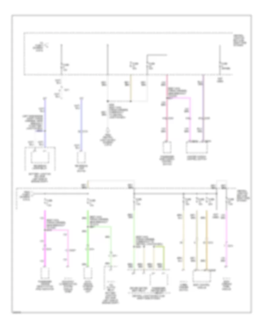
Power Distribution Wiring Diagram (5 of 5) for Ford Fiesta SE 2011
List of elements for Power Distribution Wiring Diagram (5 of 5) for Ford Fiesta SE 2011:
- (body main wiring harness, in breakout to central junction box) s254
- (body main wiring harness, near breakout to c214) s261
- (body main wiring harness, near breakout to c340) s310
- (body main wiring harness, near breakout to c340) s311
- (left side engine compt wiring harness, near breakout to battery junction box) s121
- (not used)
- A/c clutch relay
- A/t
- A15
- Auto dimming interior mirror unit
- Battery junction box (bjb) (left side of engine compt)
- Body control module
- C133
- C211
- C212
- C213
- C214
- C2280b
- C3007
- C339 b14
- C340 a15
- C504a
- C504c
- Central junction box (cjb) (right side of dash)
- Driver heated seat relay
- From central junction box (diagram 2 of 5)
- From fuse 6 l (diagram 5 of 5)
- Fuse (spare)
- Fuse 10a
- Fuse 15a
- Fuse 20a
- Fuse 30a
- Fuse 7.5a
- M/t
- Master window control switch
- Occupant classification system module (ocsm)
- Passenger air bag deactivation (pad) indicator
- Passenger heated seat relay
- Passenger side window control switch
- Reversing lamp switch
- Reversing lamps relay
- Roof opening panel module
- S255 (body main wiring harness, in breakout to central junction box)
- To fuse 4 (diagram 5 of 5)
- Wiper/ washer switch