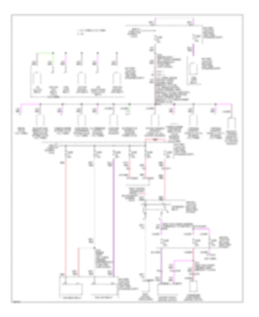
POWER DISTRIBUTION
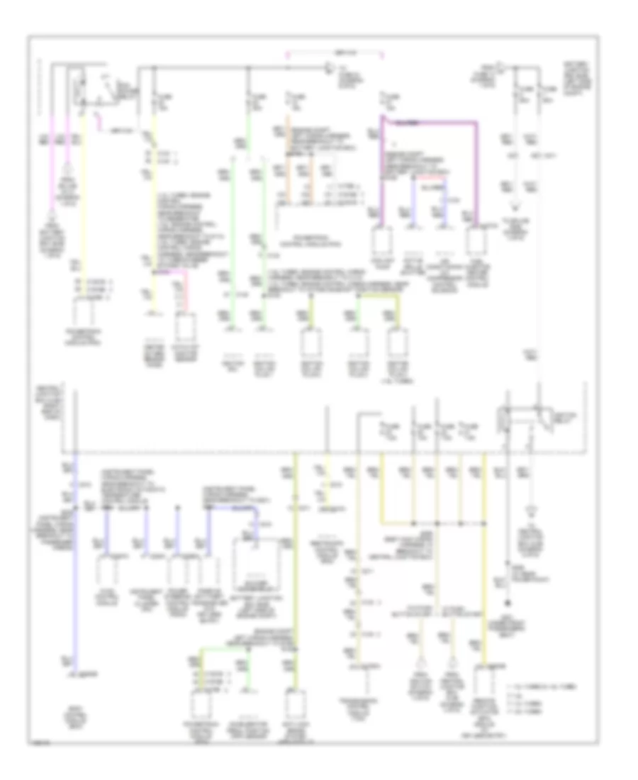
Power Distribution Wiring Diagram (1 of 6) for Ford Fiesta Titanium 2014

List of elements for Power Distribution Wiring Diagram (1 of 6) for Ford Fiesta Titanium 2014:
- (1.0l turbo)
- (1.6l)
- (1.6l: engine control wiring harness, near breakout to g114) (1.0l turbo: engine control wiring harness, near breakout to heated oxygen sensor) s100
- (engine compartment left wiring harness, near breakout to battery junction box) s114
- 1.0l turbo
- 1.6l & 1.6l turbo
- A/c clutch relay
- Anti-lock brake system (abs) module
- Auxiliary relay box (w/ electric booster heater) (left front of engine compt)
- Battery
- Battery junction box (bjb) (left side of engine compt)
- Battery monitoring sensor (1.0l turbo & 1.6l turbo)
- Blower motor relay
- Body control module (bcm)
- C1100a
- C133
- C140
- C1617a
- C1617b
- C1617c
- C1617d
- C1617e
- C1750a
- C175b
- C210
- C211
- C2280a
- C2280c
- C2368c
- Cooling fan relay
- Electric booster heater relay 1
- Electric booster heater relay 2
- Evaporative emission canister vent valve
- Fuse 10a
- Fuse 15a
- Fuse 20a
- Fuse 30a
- Fuse 3a
- Fuse 40a
- Fuse 60a
- Fuse 7.5a
- Generator
- High current battery junction box (bjb) (at battery)
- High fan control (hfc) relay
- In-line fuse 1 (on battery positive (+) post)
- Low fan control (lfc) relay
- Mega fuse 1 450a
- Mega fuse 2 60a
- Mega fuse 3 200a
- Mega fuse 4 70a
- Mega fuse 5 50a
- Power steering control module (pscm)
- Powertrain control module (pcm) (1.6l)
- Red
- S156 (1.0l turbo) red (engine control wiring harness, near breakout to heated oxygen sensor)
- Starter inhibit relay
- Starter motor
- To battery junction box (bjb) (diagram 2 of 6)
- To fuse 17 (diagram 6 of 6)
- To fuse 5 (diagram 2 of 6)
- Transmission control module (tcm) (a/t)
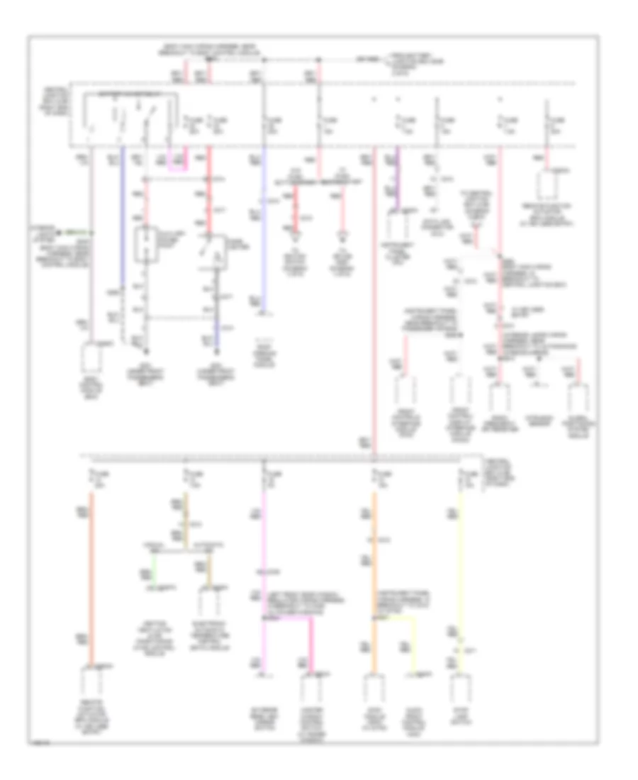
Power Distribution Wiring Diagram (2 of 6) for Ford Fiesta Titanium 2014
List of elements for Power Distribution Wiring Diagram (2 of 6) for Ford Fiesta Titanium 2014:
- (1.0l turbo: engine control wiring harness, near breakout to generator) (1.6l: engine control wiring harness, near breakout to g114) (1.6l turbo: engine control wiring harness, near breakout to turbocharger bypass valve) s103
- (1.6l turbo: engine control wiring harness, near breakout to c110) (1.0l turbo: engine control wiring harness, near breakout to intake camshaft position sensor) s108
- (engine compt left wiring harness, near breakout to battery junction box) s165
- (engine compt left wiring harness, near breakout to g109) s122
- (instrument panel wiring harness, near breakout to g201) s213
- 1.0l turbo
- 1.0l turbo & 1.6l turbo
- 1.6l
- 1.6l turbo
- Accelerator pedal position (app) sensor
- Active grille shutter
- Air conditioning a/c compressor control solenoid
- Anti-lock brake system (abs) module
- Battery junction box (bjb) (left side of engine compt)
- Blower motor relay
- Body control module (bcm)
- C1273a
- C133
- C1381b
- C140
- C1750a
- C175b
- C1915b
- C210
- C211
- C212
- C220a
- C2280b
- C2357a
- C2368a
- C310a
- C3503b
- Catalyst monitor sensor
- Central junction box (cjb) (right end of dash)
- Coolant pump
- From a fuse 10 (diagram 1 of 6)
- From battery junction box (bjb) (diagram 1 of 6)
- From central junction box (cjb) (diagram 4 of 6)
- From ignition switch (diagram 4 of 6)
- From splice s114 (diagram 1 of 6)
- Fuel injector heater control module
- Fuse 10a
- Fuse 15a
- Fuse 20a
- Fuse 60a
- Fuse 7.5a
- G301 (under front passenger's seat)
- Heated oxygen sensor (ho2s)
- Hvac control module
- Ignition coil
- Ignition coil-on plug 1
- Ignition coil-on plug 2
- Ignition coil-on plug 3
- Ignition coil-on plug 4 (1.6l turbo)
- Ignition relay
- Instrument panel cluster (ipc)
- Passive anti-theft transceiver (w/o keyless entry)
- Pcm power relay
- Power steering control module (pscm)
- Powertrain control module (pcm)
- Remote function actuator (rfa) module (w/ keyless entry)
- Restraints control module (rcm)
- S228
- S239 (instrument panel wiring harness, near breakout to passenger airbag)
- S256 (w/ rear power point)
- S259 (body main wiring harness, in breakout to central junction box)
- To central junction box (cjb) (diagram 5 of 6)
- To fuse 24 (diagram 6 of 6)
- To splice s252 (diagram 3 of 6)
- Transmission control module (tcm)
- W/ push button start
- W/o push button start
Power Distribution Wiring Diagram (3 of 6) for Ford Fiesta Titanium 2014
List of elements for Power Distribution Wiring Diagram (3 of 6) for Ford Fiesta Titanium 2014:
- (body main wiring harness, near breakout to body control module) s252
- (instrument panel wiring harness, in breakout to c212) (w/ sync) s201
- (instrument panel wiring harness, near breakout to passenger air bag) s225
- (interior lamps wiring harness, near breakout to auto-dimming interior mirror) s914
- (left front door window regulator wiring harness, in breakout to c339) (w/ power windows) s504
- Audio front control module (acm)
- Automatic a/c
- Auxiliary power point
- Battery saver relay
- Body control module (bcm)
- Breakout to central junction box)
- C211
- C212
- C213
- C220a
- C2280c
- C228a
- C2357a
- C240a
- C314
- C317
- C339 a8
- C3503a
- C504a
- Central junction box (cjb) (right end of dash)
- Cigar lighter
- Data link connector (dlc)
- Electronic automatic temperature control (eatc) module
- Exterior rear view mirror switch
- From battery junction box (bjb) f (diagram 2 of 6)
- Front control/ display interface module (fcdim)
- Front controls interface module (fcim)
- Fuse 10a
- Fuse 15a
- Fuse 20a
- Fuse 5a
- Fuse 7.5a
- G301 (under front passenger's seat)
- Global positioning system module
- Heating ventilation & air conditioning (hvac) control module
- Instrument panel cluster (ipc)
- Interior lights system
- Intrusion sensor
- Manual a/c
- Master window control switch (w/ power window)
- Radio frequency (rf) receiver
- Red
- Remote function actuator (rfa) module (w/ keyless entry)
- Roof opening panel module
- S248 (body main wiring harness, near breakout to body control module)
- S256
- Stop lamp switch
- Sync module (apim) (w/ sync)
- To central jinction box (cjb) (diagram 6 of 6)
- To ignition switch (diagram 4 of 6)
- To splice s253 (diagram 4 of 6)
- W/ keyless entry
- W/ push button start
- W/o push button start
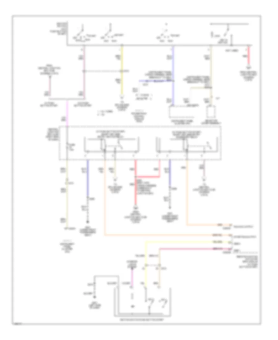
Power Distribution Wiring Diagram (4 of 6) for Ford Fiesta Titanium 2014
List of elements for Power Distribution Wiring Diagram (4 of 6) for Ford Fiesta Titanium 2014:
- (instrument panel wiring harness, near breakout to g201) (a/t) s245
- (instrument panel wiring harness, near breakout to g201) s230
- (not used)
- (w/ push button start) smart keyless entry accessory relay
- (w/ push button start) smart keyless entry ignition relay
- 1.0l turbo
- 1.6l
- A/t
- Acc
- C1381b
- C175b
- C210
- C212
- C220a
- C3503b
- C3503c
- Central junction box (cjb) (right end of dash)
- From central junction box (cjb) (diagram 3 of 6)
- From central junction box (cjb) (diagram 4 of 6)
- From central junction box (diagram 3 of 6)
- Fuse 7.5a
- G201 (left side of dash)
- G301 (under front passenger's seat)
- Ignition switch (w/o push button start)
- Ignition switch-push button start
- Instrument panel cluster (ipc)
- Interior lights system
- Key in ignition
- Lock
- Off
- Powertrain control module (pcm)
- Red
- Remote function actuator (rfa) module (w/ push button start)
- Run
- Run/acc output
- S218
- S253 (body main red wiring harness, in breakout to central junction box)
- S256
- Selector lever assembly
- Ssb 1
- Ssb 2
- Start
- Start/run output
- Sw 1
- Sw 2
- To central junction box (cjb) (diagram 4 of 6)
- To splice s259 (diagram 2 of 6)
- W/ push button start
- W/o push button start
Power Distribution Wiring Diagram (5 of 6) for Ford Fiesta Titanium 2014
List of elements for Power Distribution Wiring Diagram (5 of 6) for Ford Fiesta Titanium 2014:
- (body main wiring harness, in breakout to central junction box) s254
- (body main wiring harness, near breakout to c214) s261
- (body main wiring harness, near breakout to c340) s310
- (engine compt left wiring harness, near breakout to battery junction box) s121
- (interior lamps wiring harness, in breakout to c214) (w/ rain sensor) s915
- 1.0l turbo
- 1.6l
- 1.6l turbo
- A/t
- Auto dimming interior mirror unit
- Auxiliary relay box (left front of engine compt)
- Battery junction box (bjb) (left side of engine compt)
- Body control module (bcm)
- C133
- C140
- C211
- C212
- C213
- C214
- C2280b
- C3007
- C934
- Central junction box (cjb) (right end of dash)
- Driver heated seat relay
- Electric booster heater relay 1
- Electric booster heater relay 2
- From central junction box (cjb) (diagram 2 of 6)
- From fuse 6 l (diagram 5 of 6)
- Fuse 10a
- Fuse 15a
- Fuse 20a
- Fuse 7.5a
- M/t
- Occupant classification system module (ocsm)
- Passenger air bag deactivation (pad) indicator
- Passenger heated seat relay
- Rain sensor module (if equipped)
- Rear parking aid camera (w/ rearview camera)
- Reversing lamp switch
- Reversing lamps relay
- Roof opening panel module
- S166 (engine compt left wiring harness, near breakout to g107)
- To fuse 2 (diagram 5 of 6)
- Windshield wiper/ washer switch
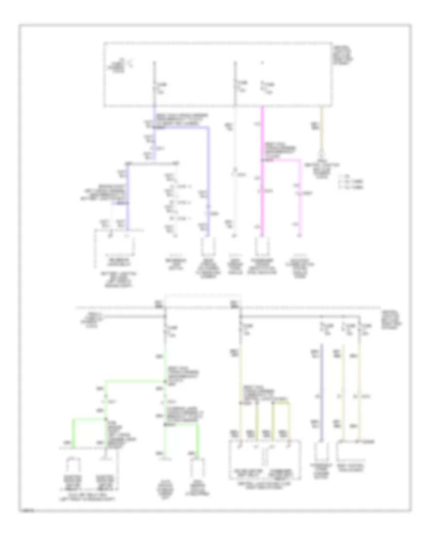
Power Distribution Wiring Diagram (6 of 6) for Ford Fiesta Titanium 2014
List of elements for Power Distribution Wiring Diagram (6 of 6) for Ford Fiesta Titanium 2014:
- (1.0l turbo: engine control wiring harness, near breakout to c146) (1.6l: engine control wiring harness, near breakout to fuel injector 2) (1.6l turbo: engine control wiring harness, near breakout to turbocharger bypass valve) s109
- (body main wiring harness, in breakout to central junction box) s282
- (not used)
- 1.0l turbo & 1.6l turbo
- 1.6l
- A/c clutch relay
- A15 c339
- Accessory relay
- Air conditioning (a/c) clutch relay
- B14
- Battery junction box (bjb) (left side of engine compt)
- Body control module (bcm)
- C133
- C140
- C211
- C212
- C2280a
- C2280c
- C2280d
- C340 a15
- C504a
- C504c
- Central junction box (bjb) (right end of dash)
- Central junction box (cjb) (right end of dash)
- Cooling fan relay (1.6l & 1.6l turbo)
- Degas valve (1.6l turbo)
- Electronic compressor bypass valve (1.0l turbo)
- Evaporative emission canister purge valve
- Exhaust gas reorculation (egr) cooler bypass valve (1.6l turbo)
- Exhaust variable camshaft timing (vct) oil control solenoid
- Fog lamp relay
- From fuse 18 m (diagram 2 of 6)
- From n fuse 6 (diagram 1 of 6)
- From o splice s262 (diagram 3 of 6)
- Fuel pump relay
- Fuse 10a
- Fuse 15a
- Fuse 20a
- Fuse 30a
- Fuse 60a
- Fuse 7.5a
- High beam relay
- High fan control (hfc) relay
- Intake variable camshaft timing (vct) oil control solenoid
- Low fan control (lfc) relay
- Master window control switch
- Oil pressure control solenoid (1.0l turbo)
- Passenger door window control switch
- Red
- S120 (engine compt left wiring harness, near breakout to battery junction box)
- S163 (engine compt left wiring harness, near breakout to battery junction box)
- S311 (body main wiring harness, near breakout to c340)
- Turbocharger bypass valve (1.6l turbo)
- Turbocharger wastegate regulating valve solenoid (tcwrvs) (1.0l turbo)
- Variable camshaft timing 11 (vct11) solenoid (1.0l turbo)
- Variable camshaft timing 12 (vct12) solenoid (1.0l turbo)
- Wastage control solenoid