POWER DISTRIBUTION
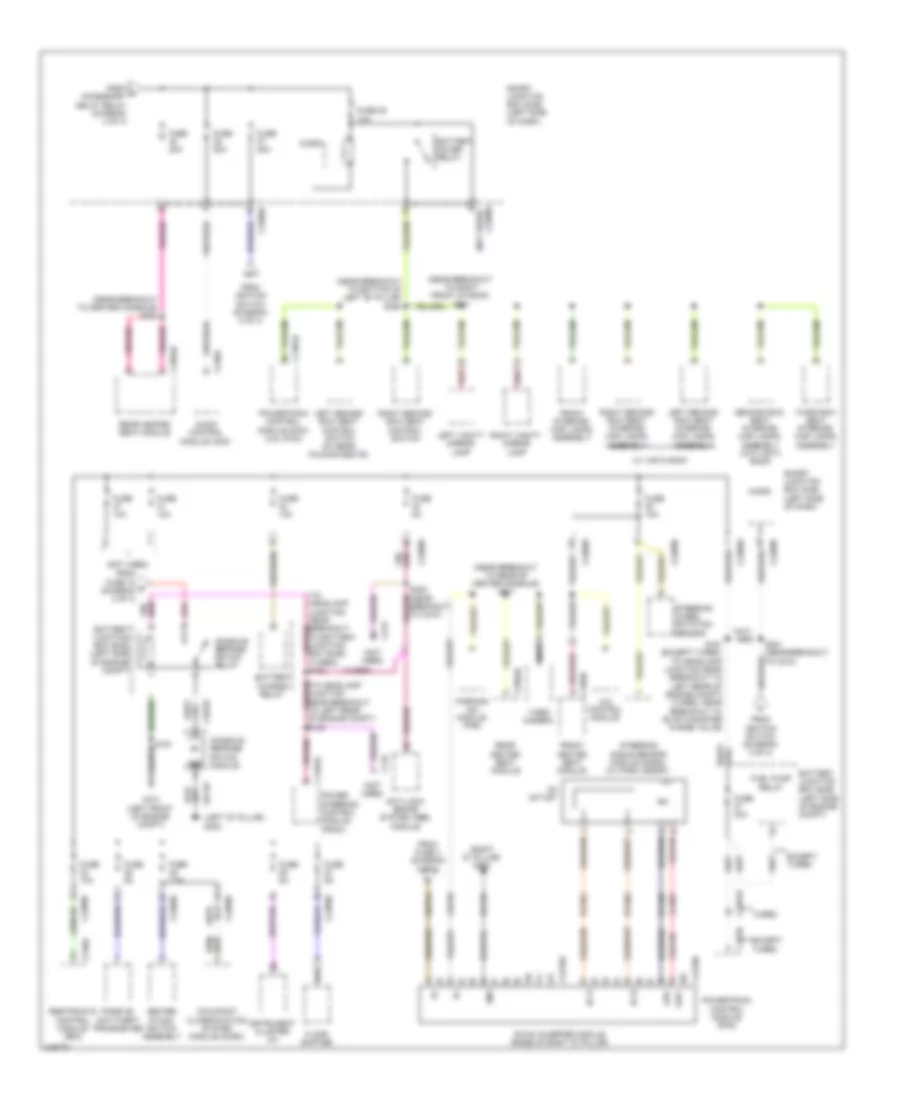
Power Distribution Wiring Diagram (1 of 4) for Ford Flex SE 2010

List of elements for Power Distribution Wiring Diagram (1 of 4) for Ford Flex SE 2010:
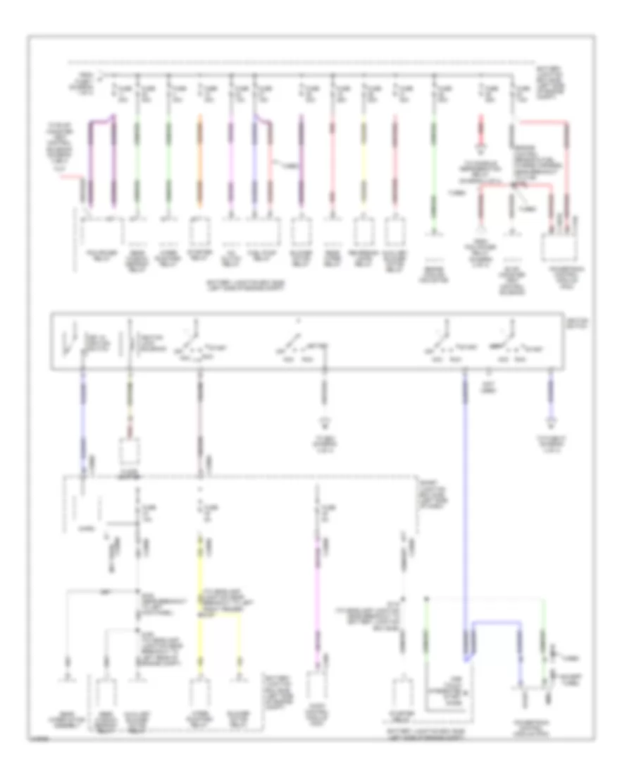
Power Distribution Wiring Diagram (2 of 4) for Ford Flex SE 2010
List of elements for Power Distribution Wiring Diagram (2 of 4) for Ford Flex SE 2010:
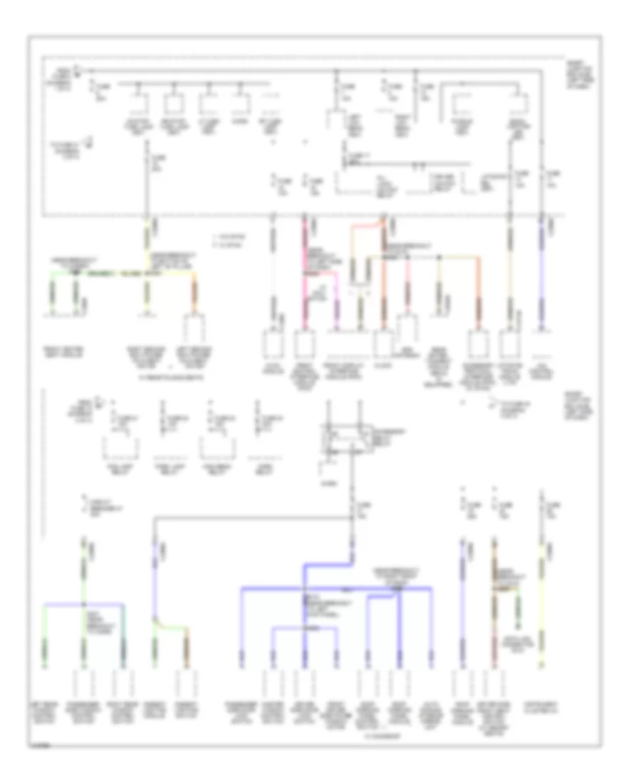
Power Distribution Wiring Diagram (3 of 4) for Ford Flex SE 2010
List of elements for Power Distribution Wiring Diagram (3 of 4) for Ford Flex SE 2010:
Power Distribution Wiring Diagram (4 of 4) for Ford Flex SE 2010
List of elements for Power Distribution Wiring Diagram (4 of 4) for Ford Flex SE 2010: