POWER DISTRIBUTION
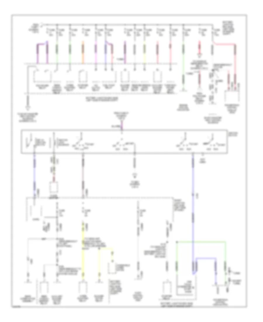
Power Distribution Wiring Diagram (1 of 4) for Ford Flex SE 2011

List of elements for Power Distribution Wiring Diagram (1 of 4) for Ford Flex SE 2011:
- (in breakout to subwoofer) s307
- (left side of engine compt) battery junction box (bjb)
- (near breakout to c3050) s326
- (not used)
- (to headlamp junction near breakout to auxiliary relay box) s194
- (to headlamp junction near breakout to left front of engine compt, on transaxle) s181
- (turbo: near breakout to coil on plug 4) (except turbo: to headlamp junction near breakout to left front of engine compt, on transaxle) s157
- 3rd rao seat enable (fet)
- Adjustable pedal switch
- Anti-lock brake system (abs) module
- Audio amplifier
- Battery
- Battery charge relay
- Battery junction box (bjb) (left side of engine compt)
- Brake pedal position (bpp) switch
- Bsi (fet)
- C1045
- C1284a
- C1285a
- C145
- C1463b
- C210
- C211
- C2280d
- C2280g
- C3049
- C3050
- C312
- C3206
- C328
- C341a
- C341b
- C411
- C4174b
- C4208c
- C510
- Driver seat module (dsm)
- Driver side front power window motor
- Driver side front seat control switch
- Exterior rear view mirror switch
- Front console power point
- Front passenger side seat control switch
- Fuse 10a
- Fuse 15a
- Fuse 20a
- Fuse 30a
- Fuse 40a
- Fuse 5a
- Fuse 7.5a
- Fuse 80a
- G203 (center of dash)
- G300 (right "d" pillar)
- Generator
- Instru- ment panel power point
- Interior lighting (fet)
- Key pad illum (fet)
- Keypad switch assembly
- Left headlamp assembly
- Liftgate/ trunk module (ltm)
- Micro
- Power steering control module (pscm)
- Rear console power point
- Rear power point
- Red
- Right headlamp assembly
- Right low beam (fet)
- S182 (to headlamp junction near breakout to left front of engine compt, on transaxle)
- S183 red (to headlamp junction near breakout to auxiliary relay box)
- S383
- Smart junction box (sjb) (left side of dash)
- Starter motor
- To dc/ac inverter module (diagram 4 of 4)
- To fuse 11 (diagram 2 of 4)
- To fuse 6 (diagram 3 of 4)
- Trailer brake control (tbc) module
- Trailer tow left turn relay
- Trailer tow park lamp relay
- Trailer tow right turn relay
- W/ 6 way power seat
- W/ memory
- W/o 6 way power seat
- W/o memory
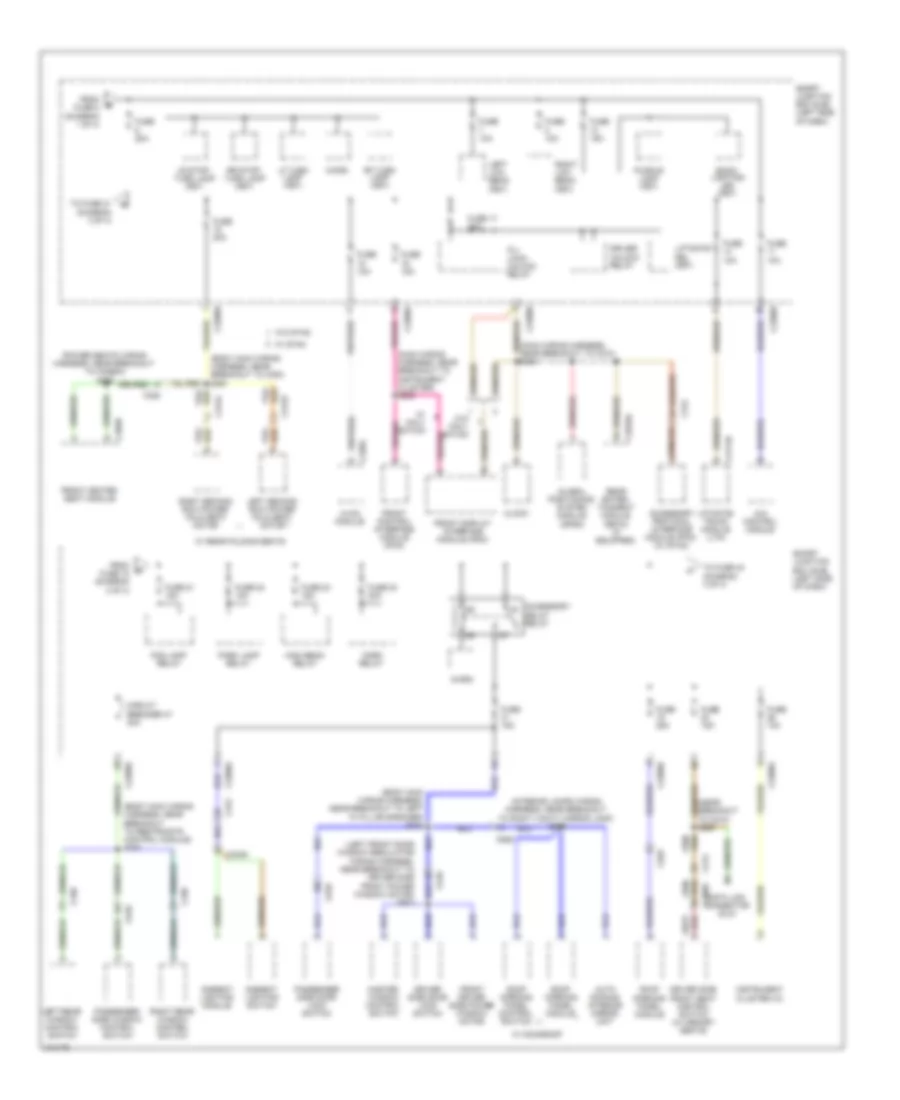
Power Distribution Wiring Diagram (2 of 4) for Ford Flex SE 2011
List of elements for Power Distribution Wiring Diagram (2 of 4) for Ford Flex SE 2011:
- (near breakout to c139) s150
- (not used)
- A/c clutch relay
- Acc
- Acc run
- Audio control module (acm)
- Auxiliary blower motor relay
- Battery junction box (bjb) (left side of engine compt)
- Blower motor relay
- C1381b
- C175b
- C210
- C211
- C2280a
- C2280b
- C2280d
- C2280e
- C240a
- C312
- C315
- C983
- Engine cooling fan motor
- Evap canister vent control solenoid
- Except turbo
- Floor shifter
- From fuse 27 (diagram 4 of 4)
- From fuse 7 (diagram 1 of 4)
- From pcm power relay (diagram 2 of 4)
- Fuel pump relay
- Fuse 10a
- Fuse 15a
- Fuse 20a
- Fuse 25a
- Fuse 30a
- Fuse 40a
- Fuse 5a
- Fuse 7.5a
- Fuse 80a
- Ignition lock solenoid
- Ignition switch
- Key in ignition switch
- Micro
- Off
- One touch integrated start diode
- Pcm power relay
- Powertrain control module (pcm)
- Rear window defrost relay
- Rear wiper motor assembly
- Rear wiper relay
- Red
- Reversing lamps relay
- Run
- S116 (to headlamp junction near breakout to battery junction box (bjb))
- S193 (near breakout to anti-lock brake system module)
- S345 (near breakout to left kick panel)
- Smart junction box (sjb) (left side of dash)
- Smrc
- Start
- Starter relay
- Third row power seat relay
- To console refrigeration relay (diagram 4 of 4)
- To evap canister vent control solenoid (diagram 2 of 4)
- To s221 (diagram 4 of 4)
- Turbo
- Used) (not
- Windshield wiper motor
- Wiper run/park relay
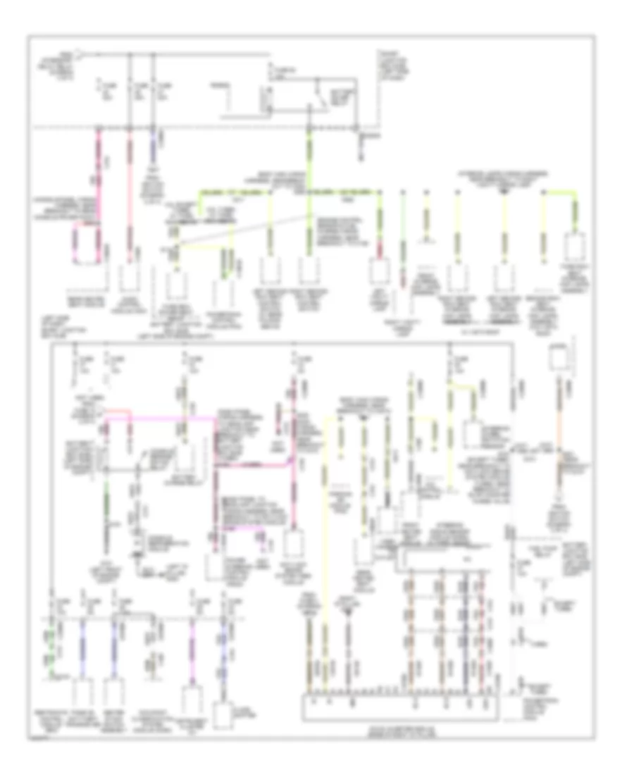
Power Distribution Wiring Diagram (3 of 4) for Ford Flex SE 2011
List of elements for Power Distribution Wiring Diagram (3 of 4) for Ford Flex SE 2011:
- (body main wiring harness, near breakout to c354) s361
- (body main wiring harness, near breakout to left "a" pillar speaker) s318
- (body main wiring harness, near breakout to restraints control module) s347
- (interior lamps wiring harness, near breakout to right vanity mirror lamp) s906
- (left front door window regulator wiring harness, near breakout to driver side front power window motor) s503
- (main wiring harness, near breakout to c210) s240
- (main wiring harness, near breakout to instrument cluster) s230
- (near breakout to c210) s220
- (power seats wiring harness, near breakout to c3265a) s355
- 4x4 control module
- Accessory delay relay
- Accessory protocol interface module (fpim) (w/ sync)
- All lock/ unlock relay
- Ambient lighting module
- Ambient lighting switch
- Auto dimming interior mirror unit
- Back- lighting led (fet)
- C213
- C2280a
- C2280b
- C2280d
- C228a
- C2949a
- C3050
- C312
- C3133
- C3134
- C3249
- C328
- C339
- C340
- C359b
- C4174b
- C510
- C610
- C925
- Circuit breaker 47 30a
- Clock
- Data link connector (dlc)
- Driver side door lock switch
- Driver side front seat control switch (w/ memory seats)
- Driver unlock relay
- Fog lamp relay
- From fuse 18 (diagram 3 of 4)
- From fuse 8 (diagram 1 of 4)
- Front control interface module (fcim)
- Front display interface module (fdim)
- Front driver side power window motor
- Front heated seat module
- Fuse 10a
- Fuse 15a
- Fuse 17 20a
- Fuse 20a
- Fuse 21 15a
- Fuse 22 15a
- Fuse 23 15a
- Fuse 24 20a
- Fuse 25a
- Global positioning system module (gpsm)
- High beam relay
- Horn relay
- Hvac module
- Instrument cluster (ic)
- Left low beam (fet)
- Left rear window control switch
- Left second row power fold seat motor
- Lf turn lamp (fet)
- Liftgate rel (fet)
- Liftgate/ trunk module (ltm)
- Lr stop/ turn lamp (fet)
- Master window control switch
- Micro
- Park lamp relay
- Passenger side door lock switch
- Passenger side window control switch
- Puddle lamp (fet)
- Rear enter- tainment module (retm) (if equipped)
- Rf turn lamp (fet)
- Right low beam (fet)
- Right rear window control switch
- Right second row power fold seat motor
- Roof opening panel control switch
- Roof opening panel module
- Rr stop/ turn lamp (fet)
- Smart junction box (sjb) (left side of dash)
- To fuse 21 (diagram 3 of 4)
- To fuse 40 (diagram 4 of 4)
- W/ moonroof
- W/ navi- gation
- W/ rear folding seats
- W/ sync
- W/o navi- gation
- W/o sync
Power Distribution Wiring Diagram (4 of 4) for Ford Flex SE 2011
List of elements for Power Distribution Wiring Diagram (4 of 4) for Ford Flex SE 2011:
- (body main wiring harness, near break- out to c354) s360
- (body main wiring harness, near breakout to c3073) s311
- (console panel wiring harness, near breakout to rear console power point) s382
- (dash panel to c145 headlamp junction wiring harness, near breakout to anti-lock brake system module) s155
- (engine control sensor & fuel charge wiring harness, near breakout to c139)
- (interior lamps wiring harness, near breakout to right vanity mirror lamp) s901
- (left "d" pillar) g302
- (left side of dash) smart junction box (sjb)
- (not used)
- (right "d" pillar) g300
- 3.5l except turbo w/ third row seats
- 3.5l turbo w/ third row seats
- 4x4 control module
- Ac outlet
- Ac-a
- Ac-b
- Anti-lock brake system (abs) module
- Audio control module (acm)
- Battery charge relay
- Battery junction box (bjb) (left side of engine compt)
- Battery saver relay
- C1381b
- C145
- C1463a
- C175b
- C210
- C211
- C212
- C213
- C2280a
- C2280b
- C2280d
- C2280e
- C240a
- C310a
- C312
- C3206
- C328
- C3304b
- C359b
- C4210a
- C4210b
- C913
- C925
- Cbp35
- Center stack switch assembly
- Console refrige- ration relay
- Console refrigeration module
- Dc/ac inverter module (base of right "d" pillar)
- Except turbo
- Floor shifter
- From fuse 15 d (diagram 2 of 4)
- From fuse 4 (diagram 1 of 4)
- From h accessory delay relay (diagram 3 of 4)
- From ignition switch (diagram 2 of 4)
- Front heated seat module
- Front interior/ map lamps assembly
- Fuel pump relay
- Fuse 10a
- Fuse 20a
- Fuse 25 10a
- Fuse 5a
- Fuse 7.5a
- G101 (left front of engine compt)
- Gd148
- Gnd
- Hya01
- Hya02
- Instrument cluster (ic)
- Led+
- Led-
- Left second row seat control switch (w/ rear folding seats)
- Left second row seat interior/ map lamps assembly
- Left vanity mirror lamp
- Lya03
- Micro
- Nca
- Occupant classification system module (ocsm)
- Parking aid module (pam)
- Passive anti-theft transceiver
- Power steering control module (pscm)
- Powertrain control module (pcm)
- Rear heated seat module
- Red
- Restraints control module (rcm)
- Right second row seat control switch
- Right second row seat interior/ map lamps assembly
- Right vanity mirror lamp
- Rya03
- S161 (except turbo: near breakout to anti-lock brake system module) (turbo: near breakout to evap canister purge valve)
- S191
- S221 (near breakout to c210)
- Sbp04
- Second row seat interior/ map lamps assembly (w/o vista roof)
- Smart junction box (sjb) (left side of dash)
- Steering angle sensor module (sasm) (w/ park assist)
- Steering wheel rotation sensor
- Third row power seat relay battery junction box (bjb) (left side of engine compt)
- Third row seat interior/ map lamps assembly
- Turbo
- Video camera
- W/ vista roof