POWER DISTRIBUTION
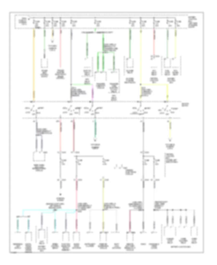
Power Distribution Wiring Diagram (1 of 4) for Ford Pickup F350 Super Duty 1999

List of elements for Power Distribution Wiring Diagram (1 of 4) for Ford Pickup F350 Super Duty 1999:
- (body harn, near breakout to rap module) s216
- (cable assembly harness, near battery) red s1001
- (engine compt harn, near breakout to speed control servo) s152
- (main harn, near breakout to main light switch) s212
- (main harn, near breakout to passenger's air bag) s241
- (rabs) (4wabs)
- 4 wheel abs
- 4 wheel anti-lock brake system module
- All lock relay
- All unlock relay
- Auxiliary power socket
- Battery
- Battery junction box
- Battery junction box (left side of engine compt)
- C142
- C147
- C277
- Daytime running lamps resistor
- Driver's unlock relay
- Fog lamp relay
- From a fuse 8 (diagram 1 of 4)
- Fuse 15a
- Fuse 20a
- Fuse 20a 50a
- Fuse 25a
- Fuse 30a
- Fuse 50a
- Generator
- Headlamp relay
- Horn relay
- Ignition switch
- Left power door lock switch
- Left rear air spring solenoid
- Lock relay block
- Main light switch
- Multi- function switch
- Park lamp relay
- Rear abs
- Rear air suspension compressor motor/ vent solenoid
- Rear air suspension compressor relay
- Rear air suspension module
- Red
- Right power door lock switch
- Right rear air spring solenoid
- S1002 (cable assembly harness, near battery)
- S108 (engine compt harn, in breakout to bjb)
- S109 (engine compt harn left side of engine compt)
- S216 (body harn, near breakout to rap module)
- Starter motor
- Starter motor relay
- To fuse 102 (diagram 2 of 4)
- To fuse 9 (diagram 1 of 4)
- Trailer tow backup lamp relay
- Trailer tow battery charge relay
- Trailer tow running lamp relay
- W/ rap
- W/o rap
- With auto lamps
Power Distribution Wiring Diagram (2 of 4) for Ford Pickup F350 Super Duty 1999
List of elements for Power Distribution Wiring Diagram (2 of 4) for Ford Pickup F350 Super Duty 1999:
- (diagram 3 of 4)
- (engine compt harn, left rear of engine compt) s112
- (engine compt harn, near breakout to bjb) s113
- (main harn, in breakout to fuse relay panel) s265
- (main harn, near breakout to instrument cluster) s222
- (main harn, near breakout to instrument cluster) s223
- (main harn, near breakout to rabs module) s217
- A/t
- Acc
- Acc delay relay
- Battery junction box
- Battery junction box (left side of engine compt)
- Blend door actuator
- Blower relay
- Blower/ flasher relay block
- C222
- C242
- C243
- C256
- C267
- C277
- Central junction box
- Central junction box (under left side of dash)
- Digital trans- mission range sensor
- Electronic shift
- From b fuse 101 (diagram 1 of 4)
- Fuel pump relay
- Function selector switch assembly
- Fuse 15a
- Fuse 20a
- Fuse 20a (rabs)
- Fuse 30a
- Fuse 40a
- Fuse 50a
- Fuse 5a
- Generic electronic module
- Ignition switch
- Instrument cluster
- Lock
- M/t
- Manual shift
- Nca
- Off
- Pcm power relay
- Power seat control switch
- Radio
- Rear air suspension module
- Rear wheel anti-lock brakes system module
- Red
- Remote anti-theft personality module
- Reversing lamp switch
- Rpo relay block
- Run
- S214 (main harn, near steering wheel rotation sensor)
- S215 (main harn, in breakout to ignition switch)
- Shift lock actuator
- Shift on the fly relay
- Speed control servo
- Start
- Starting system
- To fuse 2
- To fuse 22 (diagram 4 of 4)
- To fuse 29
- Trailer adapter (electronic brake control)
- Transfer case electric clutch relay
- Transfer case shift module
- Washer pump relay
- Windshield wiper motor
- Wiper hi/lo relay
- Wiper run/park relay
- Wot relay
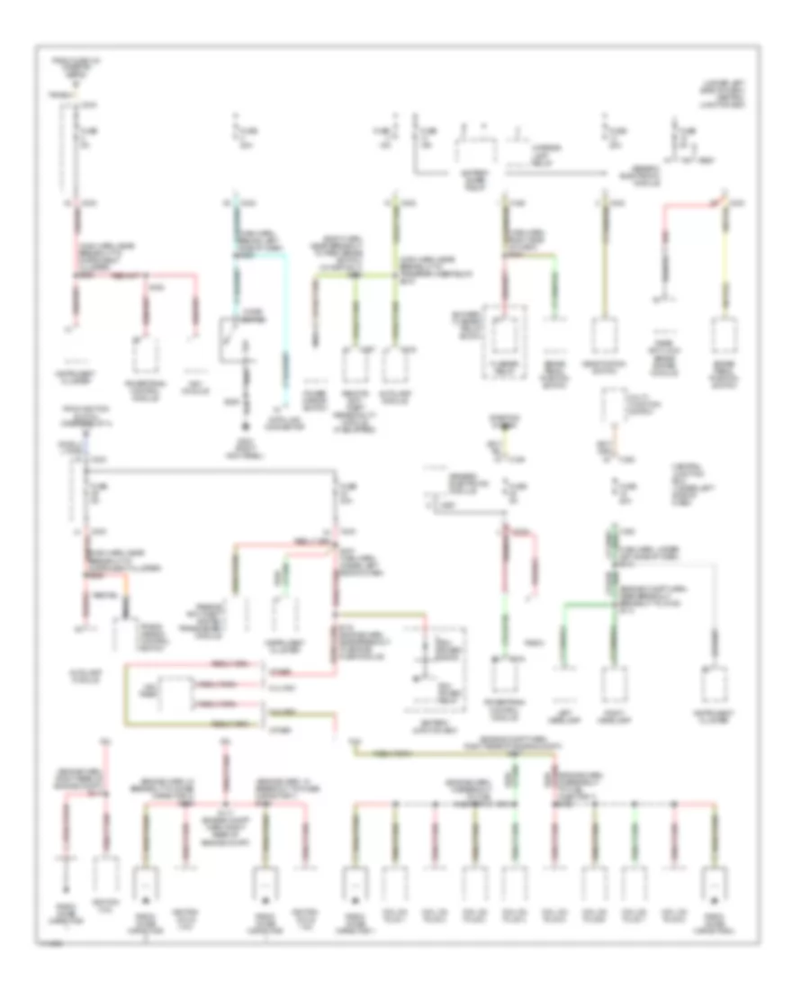
Power Distribution Wiring Diagram (3 of 4) for Ford Pickup F350 Super Duty 1999
List of elements for Power Distribution Wiring Diagram (3 of 4) for Ford Pickup F350 Super Duty 1999:
- (body harn, near breakout to park brake switch) (w/ rap only) s220
- (engine compt harn, near breakout breakout to g108) s114
- (engine compt harn, right rear of engine compt) s117
- (engine harn, in breakout to fuel injector 3)
- (engine harn, in breakout to noise capacitor 1) s118
- (engine harn, in breakout to noise capacitor 2) s119
- (engine harn, right rear of engine compt) s117
- (main harn, behind left side of dash) s289
- (main harn, near breakout to instrument cluster) s225
- (main harn, near breakout to instrument cluster) s236
- (main harn, near breakout to transfer case relay) s219
- (main harn, right side of dash) s221
- (main harn, under left side of dash) s218
- (under left side of dash) central junction box
- 4.2l
- 4.6l
- 5.4l
- 5.4l ngv
- Autolamp module
- Battery junction box
- Battery saver relay
- Blower/ flasher relay block
- Brake pedal position switch
- C174
- C216
- C242
- C243
- C257
- C267
- Central junction box (under left side of dash)
- Cigar lighter
- Coil on plug 1
- Coil on plug 2
- Coil on plug 3
- Coil on plug 4
- Coil on plug 5
- Coil on plug 6
- Coil on plug 7
- Coil on plug 8
- Data link connector
- Deactivation switch
- Flasher relay
- From fuse 103 (diagram 2 of 4)
- From ignition switch (diagram 2 of 4)
- Fuse 15a
- Fuse 20a
- Fuse 30a
- Fuse 5a
- G203 (right kick panel)
- Generic electronic module
- Ignition coil
- Ignition coils 1 & 2
- Ignition coils 3 & 4
- Injector 7) s162
- Instrument cluster
- Interior lamp relay
- Left headlamp
- Multi- function switch
- Nca
- Ngv module
- Ngv timer
- Other
- Passive anti-theft system transceiver module
- Pcm power diode
- Pcm power relay
- Power mirror switch
- Powertrain control module
- Radio
- Radio noise capacitor
- Radio noise capacitor 1
- Radio noise capacitor 2
- Rear anti-lock brake system module
- Red
- Red/
- Remote anti- theft personality module (if equipped)
- Right headlamp
- S116 (engine harn, near breakout to engine fuse module)
- S117 (engine compt harn, right rear of engine compt)
- S158
- S161
- S205
- S237 (main harn, under left side of dash)
- Starting system
- Trans- mission control switch
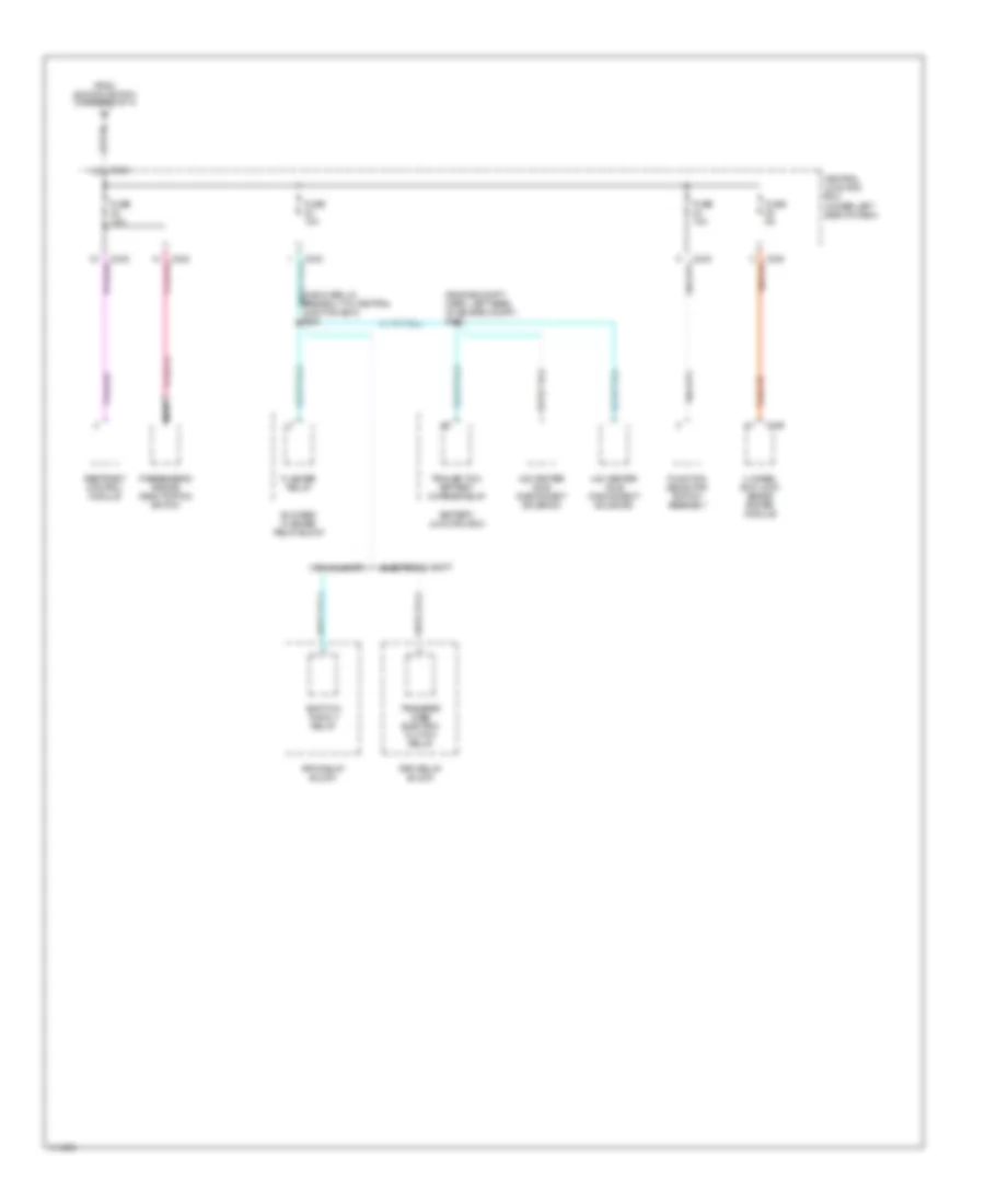
Power Distribution Wiring Diagram (4 of 4) for Ford Pickup F350 Super Duty 1999
List of elements for Power Distribution Wiring Diagram (4 of 4) for Ford Pickup F350 Super Duty 1999:
- (engine compt harn, left rear of engine compt) s120
- (main harn, in breakout to central junction box) s228
- 4 wheel anti-lock brake system module
- 4x2 center axle disconnect solenoid
- 4x4 center axle disconnect solenoid
- Battery junction box
- Blower/ flasher relay block
- C146
- C243
- C243 tan/red
- Central junction box (under left side of dash)
- Electronic shift
- Flasher relay
- From ignition switch (diagram 2 of 4)
- Function selector switch assembly
- Fuse 10a
- Fuse 5a
- Manual shift
- Nca
- Passenger's air bag deactivation switch
- Restraint control module
- Rpo relay block
- Shift on the fly relay
- Tan/red
- Trailer tow battery charge relay
- Transfer case electric clutch relay