POWER DISTRIBUTION
Power Distribution Wiring Diagram (1 of 4) for Ford Ranger 2000

List of elements for Power Distribution Wiring Diagram (1 of 4) for Ford Ranger 2000:
- (main harness, near breakout for radio) s218
- 4wabs control module
- Accessory delay relay
- Battery
- Battery junction box (left rear of engine compartment)
- Blower motor relay
- C111
- Daytime running lamps module
- Electric shift control module
- Electric shift relay
- Fog lamp relay
- From c fuse 3 (diagram 1 of 4)
- From fuse 11 b (diagram 1 of 4)
- Fuel pump relay
- Fuse 10a
- Fuse 15a
- Fuse 20a
- Fuse 30a
- Generator
- Horn relay
- Main light switch
- Maxi fuse 20a
- Maxi fuse 40a
- Maxi fuse 50a
- Mega fuse 125a
- Multi- function switch
- Nca
- Near breakout to battery junction block)
- Park lamp/ trailer tow relay
- Park lamps relay
- Pcm power relay
- Powertrain control module
- Red
- Relay box (behind dash, right of steering column)
- Remote anti-theft personality module
- S116 (dash panel to headlight jct harn, left rear of engine compartment)
- S230 (main harness, near breakout to ignition switch)
- Starter motor
- Starter motor relay
- To central junction box fuse 5 (diagram 2 of 4)
- To fuse 6 (diagram 1 of 4)
- To fuse 7 (diagram 1 of 4)
- To s232 (diagram 2 of 4)
- W/ power equipment
- W/o power equipment
- Wide open throttle/ a/c cutoff relay
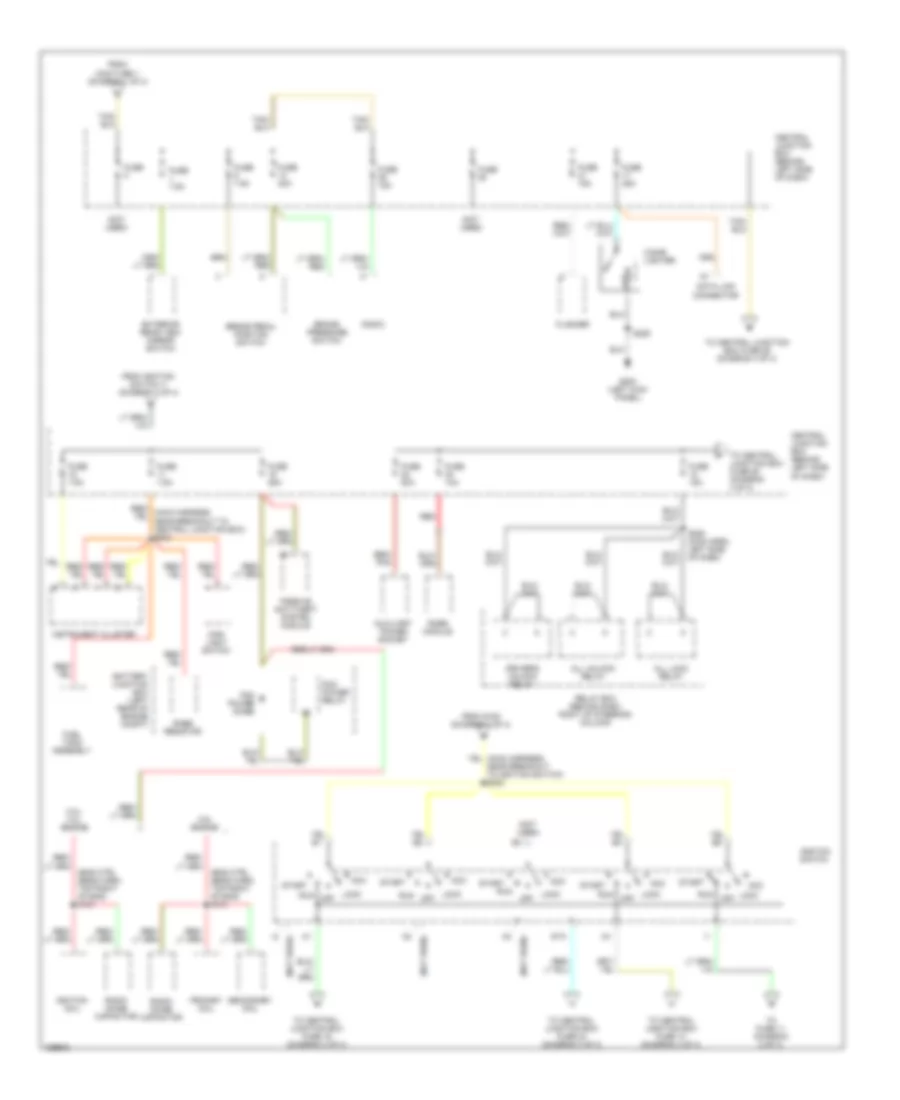
Power Distribution Wiring Diagram (2 of 4) for Ford Ranger 2000
List of elements for Power Distribution Wiring Diagram (2 of 4) for Ford Ranger 2000:
- (eng ctrl sens harn, top right of eng) s101
- (not used)
- 2.5l engine
- 3.0l/ 4.0l engine
- Acc
- All lock relay
- All unlock relay
- Auxiliary power socket
- Battery junction box (left rear of engine compt)
- Brake pedal position switch
- Brake pressure switch
- Central junction box (behind left side of dash)
- Cigar lighter
- Data link connector
- Driver's unlock relay
- Exterior rear view mirror switch
- Flasher
- From ignition switch i1 (diagram 2 of 4)
- From maxi fuse 1 (diagram 1 of 4)
- From s153 (diagram 1 of 4)
- Fuel tank assembly
- Fuse
- Fuse 10a
- Fuse 15a
- Fuse 20a
- Fuse 25a
- Fuse 7.5a
- G200 (left kick panel)
- Ignition coil
- Ignition switch
- Instrument cluster
- Lock
- Lock off
- Main light switch
- Off
- Passive anti-theft system module
- Pcm power diode
- Pcm power relay
- Primary coil
- Rabs module
- Rabs resistor
- Radio
- Radio noise capacitor
- Red
- Relay box (behind dash, right of steering column)
- Run
- S209
- S280 (main harn, left side of dash)
- Secondary coil
- Sta
- Start
- To central junction box fuse 14 (diagram 3 of 4)
- To central junction box fuse 16 (diagram 3 of 4)
- To central junction box fuse 24 (diagram 3 of 4)
- To central junction box fuse 26 (diagram 4 of 4)
- To fuse 11 (diagram 2 of 4)
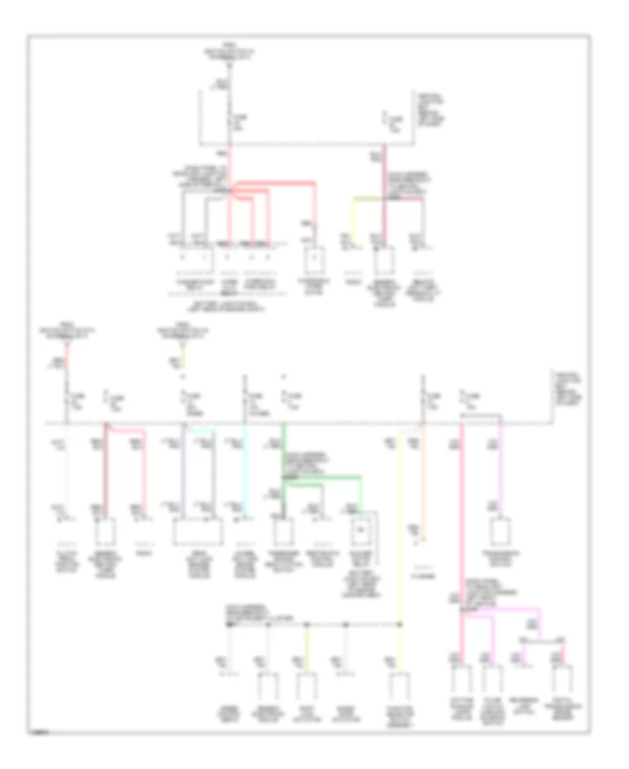
Power Distribution Wiring Diagram (3 of 4) for Ford Ranger 2000
List of elements for Power Distribution Wiring Diagram (3 of 4) for Ford Ranger 2000:
- (dash panel to headlamp junction harness, left side of firewall) s138
- (dash panel to headlight junction harness, left front of vehicle) s126
- (main harness, near breakout to central junction box) s238
- (main harness, near breakout to central junction box) s250
- (main harness, near breakout to instrument cluster) s227
- 4wheel anti-lock brake system module
- A/t
- Battery junction box (left rear of engine compartment)
- Battery junction box (left rear of engine compt)
- Blend door actuator
- Blower motor relay
- Central junction box (behind left side of dash)
- Clutch pedal position switch
- Daytime running lamps module
- Digital transmission range sensor
- Flasher
- From ignition switch a1 (diagram 2 of 4)
- From ignition switch a4 (diagram 2 of 4)
- From ignition switch sta (diagram 2 of 4)
- Function selector switch assembly
- Fuse 10a (4wabs)
- Fuse 15a
- Fuse 20a (rabs)
- Fuse 30a
- Fuse 7.5a
- Generic electronic module
- Generic electronic/ central timer module
- M/t
- Nca
- Passenger air bag deactivation switch
- Pulse vacuum hublock solenoid switch
- Radio
- Rear anti-lock brakes system module
- Red
- Remote anti-theft personality module
- Restraints control module
- Reversing lamp switch
- Shift lock actuator
- Speed control servo
- Transmission control switch
- Washer pump relay
- Windshield wiper motor
- Wiper hi/lo relay
- Wiper run/ park relay
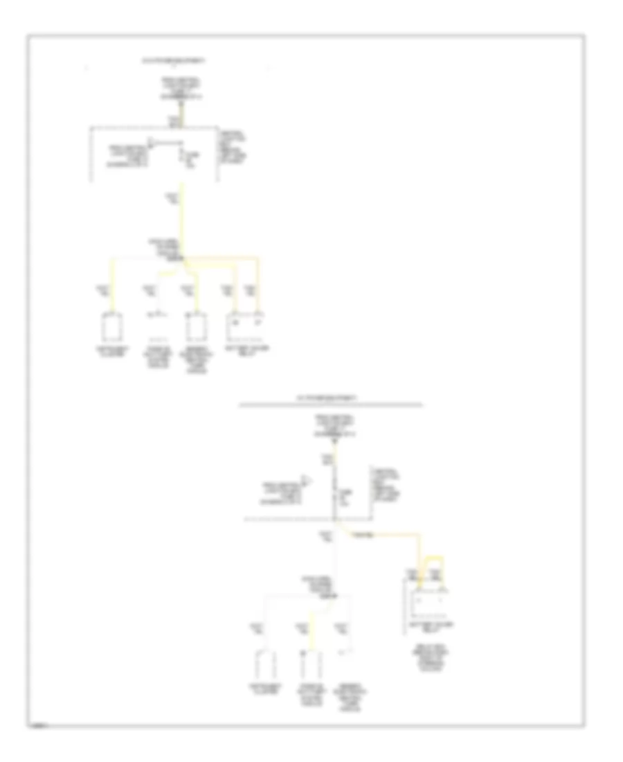
Power Distribution Wiring Diagram (4 of 4) for Ford Ranger 2000
List of elements for Power Distribution Wiring Diagram (4 of 4) for Ford Ranger 2000:
- (main harn, on rabs module) s260
- (w/ power equipment)
- (w/o power equipment)
- Battery saver relay
- Central junction box (behind left side of dash)
- F from central junction box fuse 18 (diagram 2 of 4)
- From central junction box fuse 17 (diagram 2 of 4)
- Fuse 10a
- Generic electronic/ central timer module
- Instrument cluster
- Passive anti-theft system module
- Relay box (behind dash, right of steering column)