POWER DISTRIBUTION
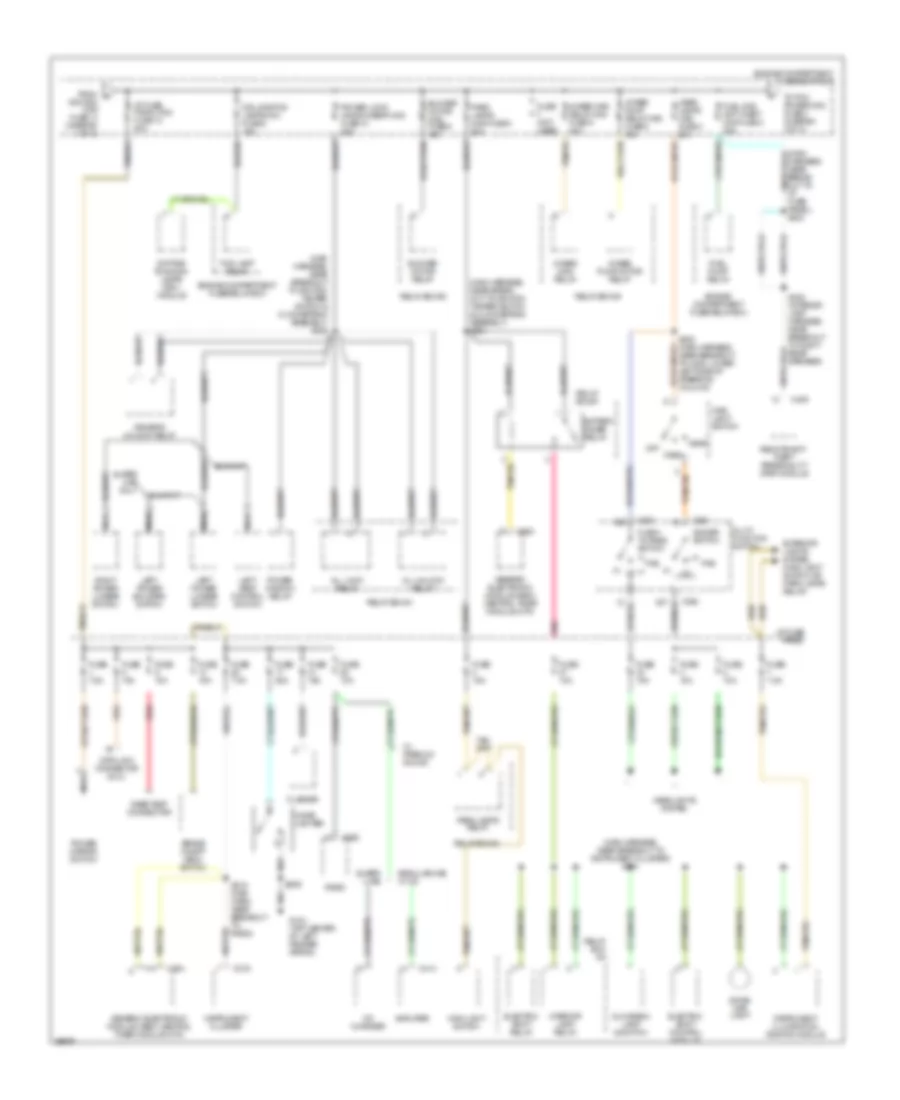
Power Distribution Wiring Diagram (1 of 3) for Ford Ranger Splash 1997

List of elements for Power Distribution Wiring Diagram (1 of 3) for Ford Ranger Splash 1997:
- (dash to headlamp harness, near break- out to engine compt fuse/ relay box) s136
- (dash to headlamp harness, near breakout to c135 & c136, left side of safety wall) s138
- (dash to headlamp harness, near breakout to ground g104, top center of left fender apron) s124
- (engine extention harn, near breakout to c114, left rear of engine) s1002
- (main harness, in break- out to ignition switch & shift lock actuator) s232
- (not used)
- 4 wheel anti- lock brake system (4wabs) main relay
- 4 wheel anti-lock brake system (4wabs) module
- A/c- heater control assembly
- A/t
- Acc
- Air bag diagnostic monitor
- Back-up lamp switch
- Battery
- Blend door actuator
- Blower motor relay
- Brake pressure switch
- C177
- C178
- C224
- C228
- C251
- C256
- C410
- Clutch pedal position (ccp) switch
- Daytime runing lamps (drl) module
- Digital transmission range (dtr) sensor
- Engine compartment fuse/relay box
- Flasher
- Fuse 10a
- Fuse 10a (4wabs)
- Fuse 15a
- Fuse 20a (rabs)
- Fuse 30a
- Fuse 7.5a
- Generator/ voltage regulator
- Generic electronic module (gem)/ central timer module (ctm)
- I/p fuse panel
- Ignition maxi fuse 14 50a
- Ignition switch
- Lock
- M/t
- Nca
- Off
- Passive de- activation (pad) module
- Power window relay
- Radio
- Rear anti- lock brake system (rabs) module
- Red
- Relay box #1
- Relay box #2
- Relay box #3
- Remote anti-theft personality (rap) module
- Run
- S126 (dash to headlamp harness, near breakout to left front park/turn lamp)
- S227 (main harness, near break- out to instrument cluster)
- S250 (main harness, near breakout to i/p fuse panel)
- Shift lock actuator
- Speed control servo/amplifier assembly
- Sta
- Start
- Starter interrupt relay
- Starter motor/ solenoid
- Starter relay
- To i/p fuse panel, fuse 15 (diagram 3 of 3)
- To i/p fuse/panel maxi fuse 13 (diagram 2 of 3)
- Trans- mission control switch (tcs)
- W/ anti- theft
- W/ pad
- W/o anti- theft
- W/o pad
- W/o rap w/ rap
- Washer pump relay
- Wind- shield wiper motor
- Wiper hi-lo relay
- Wiper run/ park relay
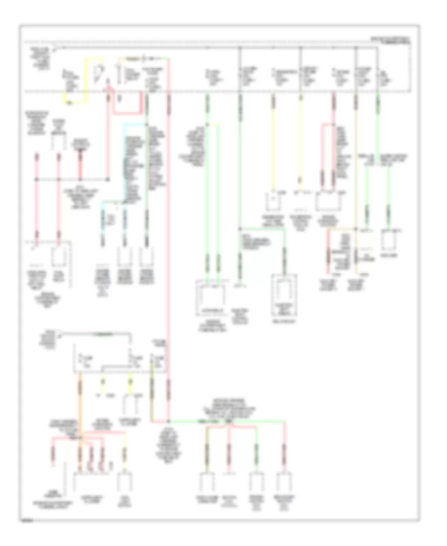
Power Distribution Wiring Diagram (2 of 3) for Ford Ranger Splash 1997
List of elements for Power Distribution Wiring Diagram (2 of 3) for Ford Ranger Splash 1997:
- (main harness, near break- out to ignition tamper switch & clockspring assembly) s224
- (main harness, near breakout to ignition tamper switch & clockspring assembly) s222
- (main harness, near breakout to instrument cluster) s221
- 4wabs main relay
- 4wabs main relay maxi fuse 6 30a
- 4wabs pump motor relay
- 4wabs pump relay maxi fuse 5 30a
- All lock relay
- All unlock relay
- Amplifier
- Battery saver relay
- Blower motor maxi fuse 9 40a
- Blower motor relay
- Brake on/off (boo) switch
- C216
- C224
- C228
- C254
- C409
- C414
- Cd changer
- Cigar lighter
- Data link connector (dlc)
- Daytime running lamps (drl) module
- Dimmer switch
- Dome/ map light
- Driver's unlock relay
- Drl sys/fog lamps mini fuse 8 15a
- Electric shift control module
- Electric shift relay
- Engine compartment fuse/relay box
- Exterior lights system (main light switch or park lamps relay)
- Flash- to-pass switch
- Flasher
- Fog lamp relay
- From a
- Fuel pump relay
- Fuel sys/ anti-theft maxi fuse 3 20a
- Fuse (not used)
- Fuse 10a
- Fuse 15a
- Fuse 25a
- Fuse 7.5a
- G104 (top center of left fender apron)
- Generic electronic module (gem)/ central timer module (ctm)
- Glove box lamp & switch
- Harness near break- out to i/p fuse panel) s223
- Head
- Head- lamps maxi fuse 4 20a
- Headlights system
- I/p fuse panal maxi fuse 13 50a
- I/p fuse panel
- Ignition maxi fuse 14 (diagram 1 of 3)
- Instrument cluster
- Instrument illumination dimming module
- Interior lamp relay
- Left power bolster switch
- Left power lumbar switch
- Left seat control switch
- Main light switch
- Multi- function switch
- Nca
- Off
- Park
- Park lamps maxi fuse 8 20a
- Park lamps relay
- Pas
- Pnk
- Power lock/ window/seat maxi fuse 10 20a
- Power mirror switch
- Power window relay
- Rabs test connector
- Radio
- Red
- Regular cab w/ cd
- Relay box #1
- Relay box #2
- Relay box #3
- Remote anti- theft personality (rap) module
- Right power lumbar switch
- S209
- S219 (main harn, near breakout to radio)
- S302 (interior lamp harness, near breakout to right rear speaker)
- Super cab
- Super cab only
- To pcm power maxi fuse 2 (diagram 3 of 3)
- W/ premium sound
Power Distribution Wiring Diagram (3 of 3) for Ford Ranger Splash 1997
List of elements for Power Distribution Wiring Diagram (3 of 3) for Ford Ranger Splash 1997:
- (engine harness, near breakout to: 2.3l, intake air temperature sensor; 3.0l, ignition coil; 4.0l, fuel injector #3) s101
- (main harness, near breakout to i/p fuse panel) s240
- 3.0l/ 4.0l only
- 4 wheel drive mini fuse 4 20a
- Air bag diagnostic monitor
- Air bag mini fuse 7 10a
- Amplifier
- Auxiliary power socket 1
- Auxiliary power socket 2
- C111
- C168
- C214
- C215
- C216
- C235
- C248
- C250
- C251
- C414
- Cd changer
- Cluster
- Electric shift control module
- Electric shift relay
- Engine compartment fuse/relay box
- Engine controls system
- Evaporative emissions (evap) canister purge solenoid
- From fuel c sys/anti- theft maxi fuse 3 (diagram 2 of 3)
- From ignition b
- Fuel pump relay
- Fuse 25a
- Fuse 7.5a
- Generator mini fuse 6 15a
- Generator/ voltage regulator
- Heated oxygen sensor (ho2s) #1
- Heated oxygen sensor (ho2s) #2
- Heated oxygen sensor (ho2s) #3 (4.0l & 3.0l only)
- Ho2s mini fuse 3 15a
- Horn maxi fuse 11 20a
- Horn relay
- I/p fuse panel
- Ignition coil (3.0l/4.0l)
- Instrument
- Instrument cluster
- Jbl mini fuse 1 20a
- Main light switch
- Memory power mini fuse 5 15a
- Nca
- Pcm power diode
- Pcm power maxi fuse 2 30a
- Pcm power relay
- Power point mini fuse 2 30a
- Powertrain control module (pcm)
- Primary ignition coil (2.3l)
- Purge flow (pf) sensor
- Rabs resistor
- Radio noise capacitor
- Red
- Regular cab w/ cd
- Relay box #1
- S109 (engine harness near break- out to: 2.3l, heated oxygen sensor #1; 4.0l & 3.0l, octane adjust shorting bar)
- S121 (dash to headlamp harness, near breakout to left headlamp)
- S134 (dash to headlamp harness, in breakout to engine compartment fuse relay box)
- S135 (dash to headlamp harness, in break- out to engine compartment fuse/relay panel)
- S200 (main harn, near break- out to ground g203, behind right cowl panel)
- S218 (main harness, near breakout to radio)
- S231 (main harn, near breakout to auxiliary power socket)
- Secondary ignition coil (2.3l)
- Super cab and regular cab w/o cd
- Switch (diagram 1 of 3)
- Wide open throttle a/c cut- off (wac) relay