POWER DISTRIBUTION
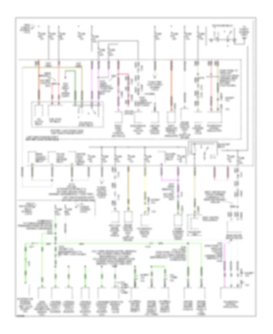
Power Distribution Wiring Diagram (1 of 5) for Ford Taurus Police Interceptor 2013

List of elements for Power Distribution Wiring Diagram (1 of 5) for Ford Taurus Police Interceptor 2013:
- (body main wiring harness, near breakout to park brake switch) s316
- (in breakout to datc hvac module) s203
- (left side of engine compt) battery junction box (bjb)
- (not used)
- (police option)
- (police rear relay jumper wiring harness, near breakout to rear flasher relay)
- Anti-lock brake system (abs) module
- Anti-lock brake system system (abs) module
- Battery
- Battery junction box (bjb) (left side of engine compt)
- Blower motor relay
- Brake pedal position (bpp) switch
- C1021a
- C133
- C144
- C1467b
- C1617a
- C1617b
- C1617c
- C1617d
- C210
- C211
- C212
- C214
- C219
- C2238
- C2239
- C228b
- C238
- C312
- C3265a
- C3381
- C3382
- C3388a
- C341a
- Decklid flashing led relay
- Driver seat module (dsm)
- Driver side front control switch (10-way)
- Driver side front seat control switch (6-way power seat)
- Dual climate controlled seat module (dcsm)
- Except police
- From body control module fuse 16 (diagram 5 of 5)
- From splice s149 (diagram 3 of 5)
- Front cigar lighter
- Front console power point
- Fuse 10a
- Fuse 20a
- Fuse 25a
- Fuse 30a
- Fuse 40a
- Fuse 50a
- Fusible link a (10 ga- red)
- Fusible link b (10 ga- red)
- G200 (under center console)
- Generator
- High current battery junction box (bjb) (on battery)
- Hvac module
- Instru- ment panel power point 2
- Instrument panel power point 1
- Left headlamp assembly (w/ hid headlamp)
- Left side spot lamp (police)
- Left tray lamp relay
- Mega fuse 100a
- Mega fuse 60a
- Nca
- Passenger side front seat control switch
- Police
- Police trunk relay center (police) (left side of engine compt)
- Power steering control module (pscm)
- Rear console power point
- Rear flasher control relay
- Rear power point
- Rear window defrost relay
- Red
- Right side spot lamp (police)
- Right tray lamp relay
- Roof opening panel module (if equipped)
- S127 (except 2.0l: near breakout to starter motor) (2.0l: near breakout to transmission fluid warmer temperature control valve)
- S128 (starter motor relay & battery ground wiring harness, near breakout to fusible link a)
- S129 (starter motor relay & battery ground wiring harness, near breakout to fusible link a)
- S341
- S414
- Starter motor
- Starter relay
- To battery junction box (diagram 3 of 5)
- To body control module (bcm) (diagram 3 of 5)
- To body control module fuse 13 (diagram 5 of 5)
- To fuse 60 (diagram 2 of 5)
- W/ 10-way power seat
- W/ 14-way power seat
- W/ 6-way & 10-way power seat
- W/ 6-way power seat
- W/ climate controlled seats
- W/ heated seats
- W/ memory
- W/o memory
- Wiper relay
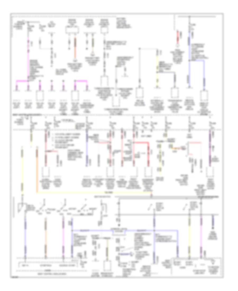
Power Distribution Wiring Diagram (2 of 5) for Ford Taurus Police Interceptor 2013
List of elements for Power Distribution Wiring Diagram (2 of 5) for Ford Taurus Police Interceptor 2013:
- (3.5l turbo: engine control sensor & fuel charge wiring harness, near breakout to c1586) (3.5l: engine control sensor & fuel charge wiring harness, near breakout to fuel injector 3) s126
- (3.5l)
- (dash panel to headlamp junction wiring harness, near breakout to battery junction box)
- (left side of engine compt) battery junction box (bjb)
- (near breakout to battery junction box)
- (near breakout to g402)
- (not used)
- (police option)
- (seat heated pad wiring harness, in breakout to rear heated seat module)
- 2.0l turbo
- 3.5l
- 3.5l turbo
- A/c clutch relay
- Anti-lock brake system (abs) module
- Battery junction box (bjb) (left side of engine compt)
- Blower motor relay
- Body control module (bcm)
- Box)
- C1041a
- C134
- C1381b
- C144
- C1467a
- C175b
- C1830
- C210
- C211
- C2238
- C2280f
- C3047
- C315
- C3304b
- Cruise control module (ccm) (w/ adaptive cruise)
- Electronics tray cooling fan
- Evap canister vent valve
- Evaporative emission (evap) purge valve
- Evaporative emission canister vent valve (except 3.5l)
- Except 2.0l turbo
- Except 3.5l
- From fuse 20 b (diagram 1 of 5)
- From pcm power d relay (diagram 2 of 5)
- Front park/ turn flashing led module
- Fuel pump (fp) relay
- Fuse 10a
- Fuse 15a
- Fuse 20a
- Fuse 30a
- Fuse 40a
- Fuse 5a
- Fuse 7.5a
- G101 (left front of engine compt)
- Heated back- light mirror relay
- Heated oxygen sensor (ho2s) 12 (3.5l turbo)
- Heated oxygen sensor (ho2s) 12 (except 3.5l turbo)
- Heated oxygen sensor (ho2s) 22
- Lighting/ siren control module
- Mass airflow/ intake air temperature sensor (3.5l)
- Nca
- Pcm power relay
- Police run/ start relay
- Police trunk release relay
- Power steering control module (pscm)
- Powertrain control module (pcm)
- Rear heated seats module
- Rear window defrost relay
- Red
- Right headlamp assembly (w/ hid headlamps)
- Run/start (fet)
- Run/start relay
- S112 (police) (starter motor relay & battery ground wiring harness, near breakout to battery)
- S122 (except 3.5l) (near breakout to battery junction box)
- S137
- S144
- S147 (near breakout to battery junction box)
- S157 (dash panel to headlamp junction wiring harness, near breakout to g102)
- S168 (3.5l turbo) (dash panel to headlamp junction wiring harness, near breakout to windshield wiper motor)
- S333
- S425
- To battery junction box (diagram 3 of 5)
- To body control module (diagram 5 of 5)
- To fuse 67 (diagram 2 of 5)
- To fuse 68 (diagram 3 of 5)
- Universal heated oxygen sensor (ho2s) 11
- Universal heated oxygen sensor (ho2s) 21
- Variable camshaft timing 11 (vct11) solenoid
- Variable camshaft timing 12 (vct12) solenoid
- Variable camshaft timing 21 (vct21) solenoid (3.5l)
- Variable camshaft timing 22 (vct22) solenoid
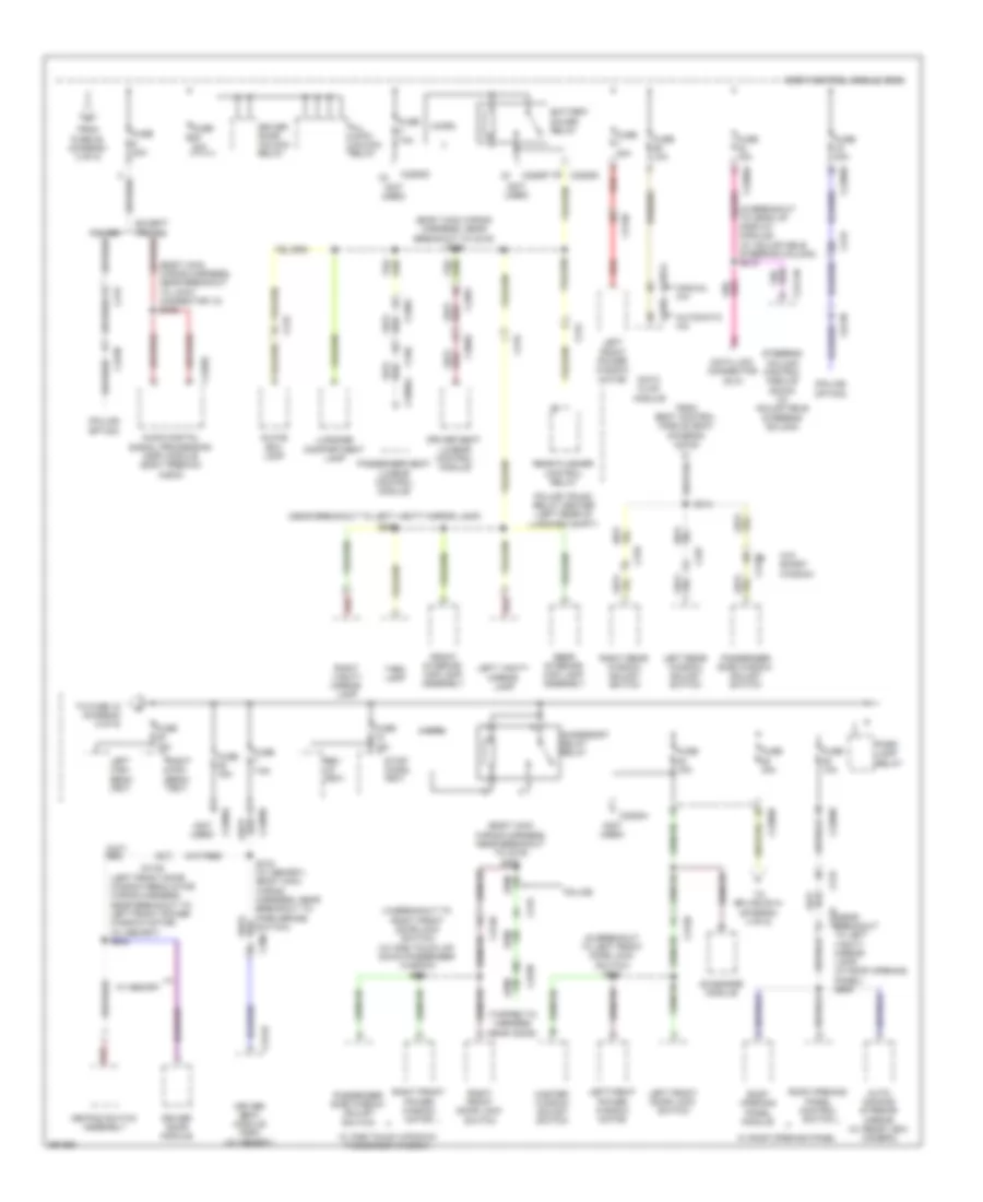
Power Distribution Wiring Diagram (3 of 5) for Ford Taurus Police Interceptor 2013
List of elements for Power Distribution Wiring Diagram (3 of 5) for Ford Taurus Police Interceptor 2013:
- (in breakout to luggage compt lid release switch) (w/ adaptive cruise control) s205
- (main wiring harness, near breakout to body control module)
- (near breakout powertrain control module) s141
- (near breakout to battery junction box)
- (near breakout to c210) s229
- (near breakout to generator) (2.0l turbo) s108
- (near breakout to high current battery junction box) (w/o intelligent access) s149
- (not used)
- (police option)
- A/c clutch relay
- Acc
- Acc/run
- Accessory protocol interface module (apim) (w/ sync)
- All wheel drive (awd) module
- Audio control module (acm)
- Battery junction box (bjb) (left side of engine compt)
- Body control module (bcm)
- Brake shift interlock
- C134
- C1381b
- C1396) s131
- C144
- C175b
- C210
- C211
- C214
- C215
- C2153c
- C2238
- C2280a
- C2280b
- C2280d
- C2280g
- C240a
- C2414a
- C263
- C300
- C3139
- C3387a
- Coil on plug (cop) 1
- Coil on plug (cop) 2
- Coil on plug (cop) 3
- Coil on plug (cop) 4
- Coil on plug (cop) 5 (except 2.0l turbo)
- Coil on plug (cop) 6 (except 2.0l turbo)
- Driver side front seat control switch
- Engine cooling fan relay hfc 1
- Engine cooling fan relay hfc 2
- Engine cooling fan relay lfc
- Except 3.5l 3.5l
- Except police
- Externally controlled variable displacement compressor (evdc)
- Floor shifter
- From battery junction box (diagram 1 of 5)
- From battery junction box (diagram 2 of 5)
- From e fuse 69 (diagram 2 of 5)
- From high current battery junction box (bjb) (diagram 1 of 5)
- Front control/ display interface module (fcdim)
- Fuse 10a
- Fuse 15a
- Fuse 20a
- Fuse 30a
- Fuse 5a
- G200 (under center console)
- Global positioning system module (gpsm)
- Grille shutter actuator
- Head up display (hud) module (w/ adaptive cruise)
- Ignition switch
- Ignition transformer capacitor 1 (3.5l turbo)
- Instrument panel cluster (ipc)
- Interior lights system
- Key in
- Key in ignition switch
- Liftgate release relay
- Lock
- Micro
- Nca
- Off
- Police
- Power seat
- Powertrain control module (pcm)
- Red
- Remote function actuator (raf) module
- Remote function actuator (rfa) module
- Remote function actuator module
- Right front power window motor
- Run
- S119
- S211 (in break- out to luggage compt lid release switch)
- S217 (in breakout
- S217 (in breakout to luggage compt lid release switch)
- S237
- Start
- Start/ stop 1
- Start/ stop 1 (active high)
- Start/ stop 2
- Start/ stop 2 (active low)
- Start/run
- Start/stop (led) (fet)
- Start/stop switch
- Steering column control module (sccm)
- Tire pressure monitor module
- To battery junction box (diagram 1 of 5)
- To fuse 5 (diagram 4 of 5)
- To keypad illu (fet) (diagram 5 of 5)
- To luggage compt lid release switch)
- Transmission fluid warmer temperature control valve
- Turbocharger (tc) wastegate regulating valve solenoid (except 3.5l)
- Turbocharger bypass valve (tcby) (except 3.5l)
- Turbocharger bypass valve 2 (tcby) (3.5l turbo)
- W/ 14-way driver
- W/ intelligent access
- W/ smart window
- W/ sync base
- W/o 14-way driver power seat
- W/o intelligent access
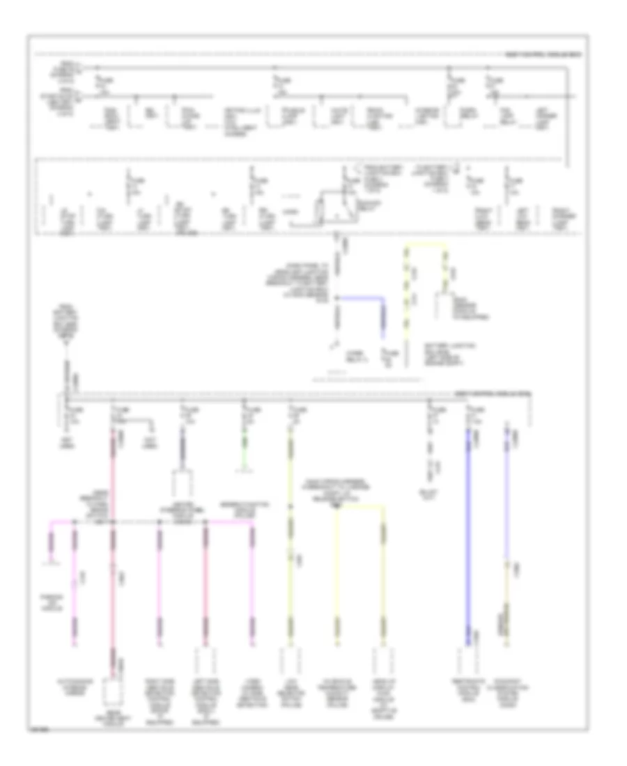
Power Distribution Wiring Diagram (4 of 5) for Ford Taurus Police Interceptor 2013
List of elements for Power Distribution Wiring Diagram (4 of 5) for Ford Taurus Police Interceptor 2013:
- (body main wiring harness, near breakout to c219) s283
- (body main wiring harness, near breakout to c219) s286
- (body main wiring harness, near breakout to joint connector 12) s409
- (in breakout to head up display module) (w/ adjustable steering column) s218
- (in breakout to left front door lock switch) s504
- (in breakout to right front door lock switch) (w/ one touch up/ down passenger window) s601
- (left front door window regulator wiring harness, near breakout to left front power window motor) (w/ memory) s502
- (near breakout c219 to left vanity mirror lamp) (w/ roof opening panel) s905
- (near breakout to left vanity mirror lamp)
- (not used)
- (police option)
- (tapped to harness near c2238)
- Accessory delay relay
- All lock/ unlock relay
- Audio digital signal processing (dsp) module (sony premium audio)
- Auto- dimming interior mirror (w/ rear view camera)
- Automatic a/c
- Battery saver relay
- Body control module (bcm)
- C215
- C219
- C2238
- C2280a
- C2280b
- C2280d
- C2280f
- C228a
- C2357a
- C2414b
- C300
- C3050
- C312
- C3138
- C3139
- C316
- C327
- C3381
- C3382
- C3386a
- C340
- C341b
- C4326c
- Data link connector (dlc)
- Datc hvac module
- Driver door module
- Driver door unlock relay
- Driver seat lumbar control module
- Driver seat module (dsm) (w/ memory)
- From body control module (bcm) (diagram 4 of 5)
- From fuse 28 (diagram 3 of 5)
- Front interior/ map lamp assembly
- Fuse 10a
- Fuse 15a
- Fuse 20a
- Fuse 30a
- Fuse 7.5a
- Glove box lamp
- Keypad switch assembly
- Left front door lock switch
- Left front power window motor
- Left high beam (fet)
- Left rear window adjust switch
- Left vanity mirror lamp
- Luggage compartment lamp
- Manual a/c
- Master window adjust switch
- Micro
- Park lamp relay
- Passenger seat lumbar control module
- Passenger side window adjust switch
- Police
- Police trunk relay center (left rear of luggage compt)
- Rear flasher control relay
- Rear interior/ map lamp assembly
- Red
- Rev lp (fet)
- Right front door lock switch
- Right front power window motor
- Right high beam (fet)
- Right rear window adjust switch
- Right vanity mirror lamp
- Roof opening panel control switch
- Roof opening panel module
- S314
- S315 (w/ memory) (body main wiring harness, near breakout to park brake switch)
- S902
- Steering column control module (sccm) (w/ adjustable steering column)
- Stop/ chmsl (fet)
- Sunshade module
- Task lamp
- To fuse 18 (diagram 5 of 5)
- To splice s314 (diagram 4 of 5)
- W/ memory
- W/ one touch up/down passenger window
- W/ roof opening panel
- W/o smart window
Power Distribution Wiring Diagram (5 of 5) for Ford Taurus Police Interceptor 2013
List of elements for Power Distribution Wiring Diagram (5 of 5) for Ford Taurus Police Interceptor 2013:
- (dash panel to headlamp junction wiring harness, near breakout to battery junction box) (w/ rain sensor) s145
- (main wiring harness, in breakout to luggage compt lid release switch) s204
- (near breakout to park brake switch) s317
- (not used)
- 2nd row seat (fet)
- Auto-dimming interior mirror
- Back lighting led (fet)
- Battery junction box (bjb) (left side of engine compt)
- Body control module (bcm)
- Bsi (fet)
- C211
- C215
- C219
- C2280b
- C2280d
- C2280e
- C2280f
- C263
- C3047
- C310a
- C3304b
- C3382
- C919
- Fog lamp relay
- From battery junction box (bjb) (diagram 2 of 5)
- From battery junction box fuse 4 (diagram 1 of 5)
- From fuse 39 k (diagram 4 of 5)
- From start/stop h (led) (fet) (diagram 3 of 5)
- Fuse
- Fuse 10a
- Fuse 15a
- Fuse 20a
- Fuse 5a
- Fuse 7.5a
- Generic function module (police)
- Head up display (hud) module (w/ adaptive cruise)
- Heated steering wheel module (hswm)
- Horn relay
- In-vehicle temperature/ humidity sensor (police)
- Interior lighting (fet)
- Keypad illum (fet) (w/o intelligent access)
- Left corner lamp (fet)
- Left low beam (fet)
- Left side obstacle detection control module (sod-l) (if equipped)
- Lf turn lamp (fet)
- Low gear selector switch (police)
- Lr stop/ turn lamp (fet)
- Lr turn lamp (fet)
- Micro
- Occupant classification system module (ocsm)
- Parking aid module
- Pcm wake up (fet)
- Puddle lamp (fet)
- Rain sensor module (if equipped)
- Rear heated seat module
- Restraints control module (rcm)
- Rf turn lamp (fet)
- Right corner lamp (fet)
- Right low beam (fet)
- Right side obstacle detection control module (sod-r) (if equipped)
- Rr stop/ turn lamp (fet) (police)
- Rr turn lamp (fet)
- Run/acc relay
- To battery junction box fuse 4 (diagram 1 of 5)
- Video camera (w/ side obstacle detection)
- White light (fet)
- Wiper relay 2