POWER DISTRIBUTION
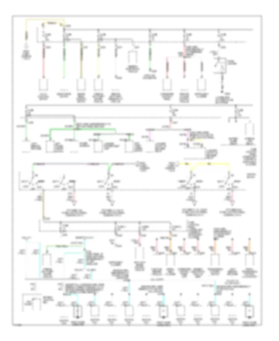
Power Distribution Wiring Diagram (1 of 3) for Ford Taurus SHO 1999

List of elements for Power Distribution Wiring Diagram (1 of 3) for Ford Taurus SHO 1999:
- (body harn, near breakout to safety belt buckle switch) s325 red
- (dash panel to headlamp junction harn, in breakout left of master cylinder) s139
- (main harn, near breakout to semi-active ride control module)
- 10a
- 175a
- 3.4l sho
- A/c clutch relay
- Anti-lock brake control module
- Autolamp headlamp relay
- Autolamp park relay
- Battery
- Battery junction box (front center of engine compt, behind radiator)
- Blower motor relay
- Cellular phone in-line fuse (in cargo area, above left rear wheelwell)
- Cellular phone support electronics
- Circuit breaker 30a
- Compact disc changer
- Daytime running lamps module
- Eam solid state relay
- Electronic crash unit
- Fuel pump relay
- Fuse 10a
- Fuse 15a
- Fuse 20a
- Fuse 30a
- Fuse 40a
- Generator
- Headlamp switch
- High speed cooling fan relay
- Horn relay
- Left lumbar seat switch
- Left seat control switch
- Low speed cooling fan relay
- Mega fuse (right side of battery junction block)
- Multi- function switch
- Nca
- Pcm relay
- Powertrain control module
- Rear control unit
- Red
- Right seat switch
- S128 (dash panel to headlamp harn, near breakout to battery junction box)
- S132 (dash panel to headlamp junction harn, near breakout to anti-lock brake control module)
- S414 (body harn, left rear wheelwell)
- S423 (radio amplifier harn, left rear wheelwell)
- Semi-active ride control module
- Starter motor
- Starter relay
- Tan/red
- To fuse 29 (fuse junction panel) (diagram 2 of 3)
- To fuse junction panel (accessory delay relay) (diagram 3 of 3)
- To ignition switch (pins b1 & b3) (diagram 2 of 3)
- To ignition switch (pins b4 & b5) (diagram 2 of 3)
- To rear window defrost relay (fuse junction panel) (diagram 3 of 3)
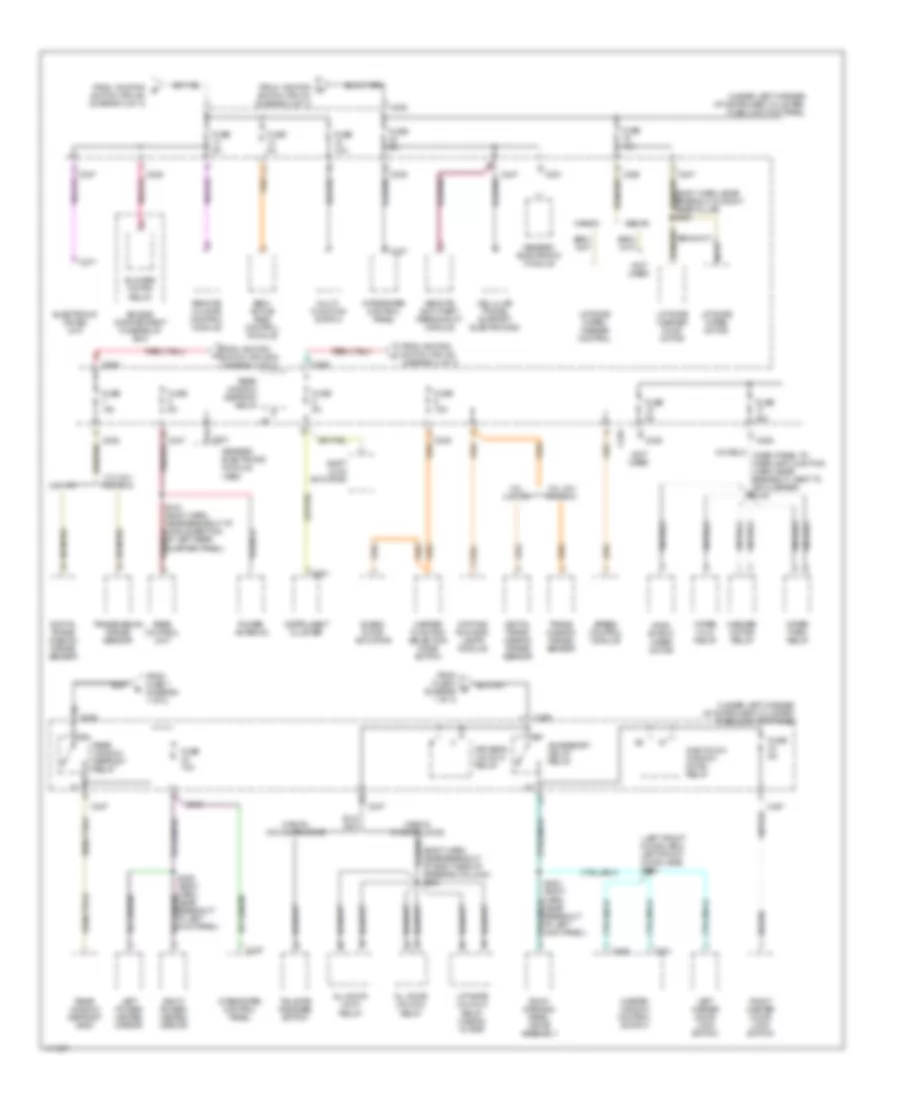
Power Distribution Wiring Diagram (2 of 3) for Ford Taurus SHO 1999
List of elements for Power Distribution Wiring Diagram (2 of 3) for Ford Taurus SHO 1999:
- (body harn, near breakout to left kick panel ground) s313
- (diagram 1 of 3)
- (engine harn, near breakout to ignition coil 5 & no 6) s161
- (engine harn, near breakout to radio noise capacitor) s163
- (fuse junction panel) (diagram 3 of 3)
- (lower side of inner glove box frame)
- (main harn, near breakout to instrument cluster) s224
- (main harn, near breakout to left of fuse junction panel) s211
- 20a
- 3.0l 12v ffv
- 3.0l 24-v & 3.4l sho only
- 3.0l 24v
- 3.4l sho
- 3.ol 12 v
- Acc
- Anti- theft disarm switch
- Anti-lock brake control module
- Battery junction box
- Battery saver relay
- Brake pedal position switch
- C2007
- C201
- C2040
- C225
- C229
- C235
- C236
- C237
- C247
- C250
- C251
- C254
- C318
- Cigar lighter
- Data link connector
- Deactivator switch
- Except 3.ol 12 v
- Flex fuel sender module
- From fuse 1 (diagram 1 of 3)
- From fuse 3 (diagram 1 of 3)
- From fuse 5 c
- Fuse
- Fuse 10a
- Fuse 11 5a
- Fuse 12 5a
- Fuse 15a
- Fuse 20a
- Fuse 5a
- Fuse 9 10a
- Fuse junction panel (under left corner of instrument cluster)
- G206
- Generic electronic module
- Generic electronic module (gem)
- Ignition coil
- Ignition coil
- Ignition switch
- Instru- ment cluster
- Instrument cluster
- Integrated control panel
- Integrated control panel (icp)
- Interior lamp relay
- Left power mirror switch
- Light sensor/ amplifier
- Lock
- Luggage compartment lamp
- Luggage compt lid release relay
- Multi- function switch
- Off
- Passive anti-theft system module
- Pcm diode
- Power antenna
- Prndl/ transmission control illumination
- Radio noise capacitor
- Radio noise capacitor 1
- Radio noise capacitor 2
- Remote anti-theft personality module
- Remote climate control module
- Run
- Sedan
- Sta
- Start
- To fuses 13, 14 & 15 (fuse junction panel) (diagram 3 of 3)
- To fuses 17, 18, 19 & 20 (fuse junction panel) (diagram 3 of 3)
- To fuses 5 & 6
- To fuses 7 & 8 (fuse junction panel) (diagram 3 of 3)
- To left headlamp)
- Transmission control switch
- W/ rap
- W/o rap
- Wagon
Power Distribution Wiring Diagram (3 of 3) for Ford Taurus SHO 1999
List of elements for Power Distribution Wiring Diagram (3 of 3) for Ford Taurus SHO 1999:
- (body harn, near breakout at right side of steering column) s204
- (body harn, near breakout in right rear pillar) s409
- (left front door harn, left front door jamb) s504
- (not used)
- (under left corner of instrument cluster) fuse junction panel
- 3.0l 12v
- 3.0l 24v 3.4l sho
- 3.0l 3.0l 12v
- Accessory delay relay
- All door lock relay
- All door unlock relay
- Blend door actuator
- Blower motor relay
- C201
- C225
- C235
- C237
- C247
- C251
- C277
- C501
- C509
- Cellular phone support electronics
- Daytime running lamps module
- Digital trans- mission range sensor
- Driver's unlock relay
- Electronic crash unit
- Engine compartment fuse/relay box
- From ignition g
- From ignition h
- From fuse 4 (diagram 1 of 3)
- From fuse 7 (diagram 1 of 3)
- From ignition switch (pin a3) (diagram 2 of 3)
- From ignition switch (pin sta) (diagram 2 of 3)
- Fuse 10a
- Fuse 15a
- Fuse 30a
- Fuse 5a
- Generic electronic module
- Generic electronic module (gem)
- Heater function selection mode switch
- Instrument cluster
- Integrated control panel
- Left master door lock switch
- Left power/ heated mirror
- Liftgate unlock relay (wagon w/ rap)
- Liftgate washer pump motor
- Liftgate wiper motor
- Liftgate wiper/ washer control
- Master window control switch
- Multi- function switch
- Nca
- One touch window down relay
- Power antenna
- Rear control unit
- Rear window defrost grid
- Rear window defrost relay
- Remote anti-theft personality module
- Remote climate control module
- Right master door lock switch
- Right power/ heated mirror
- Roof opening panel drive assembly
- S203 (body harn, near breakout at left kick panel)
- S309 (body harn, near breakout at left kick panel)
- S413 (body harn, near breakout at middle section of left rear quarter panel)
- Sedan
- Semi- active ride control module
- Shift lock actuator
- Speed control module
- Switch (pin a1) (diagram 2 of 3)
- Switch (pin a4) (diagram 2 of 3)
- Tailgate release switch
- Trans- mission range sensor
- Transmission range sensor
- Wagon
- Wagon w/o doorlocks
- Washer motor relay
- Wind- shield wiper motor
- Wiper hi/lo relay
- Wiper park relay