POWER DISTRIBUTION
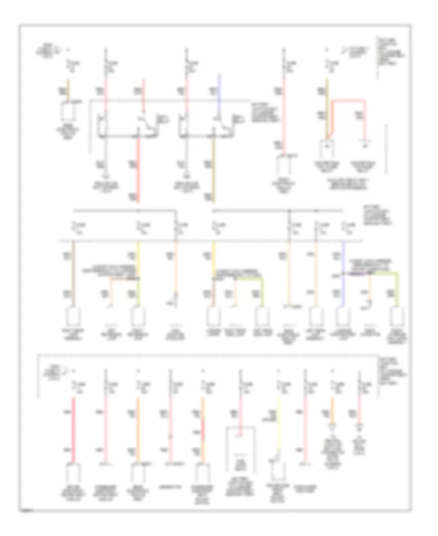
Power Distribution Wiring Diagram (1 of 4) for Ford Thunderbird 2005

List of elements for Power Distribution Wiring Diagram (1 of 4) for Ford Thunderbird 2005:
- (in body main harness, near breakout to convertible top motor) s405
- (in dash panel to headlamp junction harness, near breakout to g105) s118
- (in luggage compartment, near battery) battery junction box
- (in main harness, near breakout to passenger air bag module) s215
- (not used)
- 87a
- Auxiliary relay box 1 (behind seats, on vehicle crossbeam)
- Battery
- Battery junction box (in luggage compartment, near battery)
- C195a
- C195b
- C201a
- C201b
- C201e
- C270a
- C270b
- C270d
- C270e
- C283b
- C283d
- C4066a
- C420e
- Central junction box (behind right kick panel)
- Convertible top lower relay
- Convertible top raise relay
- Front electronic module (fem)
- Fuse 10a
- Fuse 15a
- Fuse 175a
- Fuse 30a
- Fuse 40a
- Fuse 5a
- Generator
- Glove box lamp
- Heated backlight relay
- Interior auxiliary junction box (under left side of dash)
- Left front footwell lamp
- Left front park/turn lamp
- Left front side lamp
- Left headlamp
- Mega fuse (in luggage compartment, near battery junction box)
- Passive anti-theft transceiver module
- Rear electronic module (rem)
- Rear window defrost relay
- Red
- Red c4066c
- Right front footwell lamp
- Right front park/turn lamp
- Right front side lamp
- Right headlamp
- Ssp relay
- Starter motor
- Stud dash panel (lower right end of dash)
- To fuse 12 (diagram 2 of 4)
- To ssp 3 relay (diagram 2 of 4)
- To ssp 4 relay (diagram 2 of 4)
- To stud junction box (diagram 3 of 4)
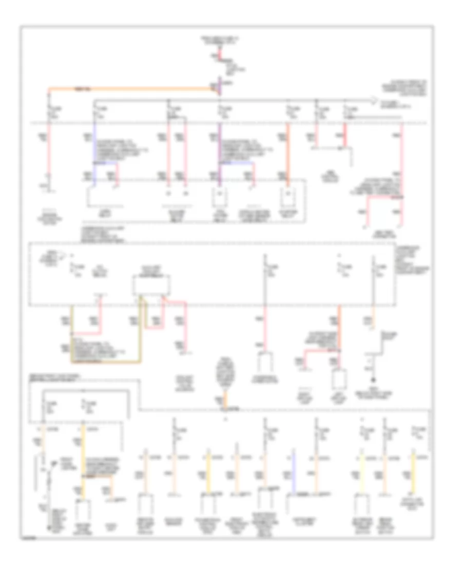
Power Distribution Wiring Diagram (2 of 4) for Ford Thunderbird 2005
List of elements for Power Distribution Wiring Diagram (2 of 4) for Ford Thunderbird 2005:
- (in body main harness, near breakout to c405) s402
- (in body main harness, near breakout to heated wiper park) s233
- (in body main harness, near breakout to luggage compartment lamp) s409
- 87a
- Auxiliary relay box 1 (behind seats, on vehicle crossbeam)
- Battery junction box (in luggage compartment, near battery)
- C102a
- C201g
- C420a
- C420e
- C420f
- Convertible top lower relay
- Convertible top raise relay
- Driver side front heated seat module
- Driver side front seat adjust switch
- From fuse 14 (diagram 2 of 4)
- From fuse 31 (diagram 1 of 4)
- From splice s407 (diagram 1 of 4)
- Front electronic module (fem)
- Front interior/ map lamps assembly
- Fuel pump relay
- Fuse 10a
- Fuse 15a
- Fuse 20a
- Fuse 30a
- Fuse 40a
- Fuse 5a
- Generator
- High mounted stoplamp
- Left rear lamp assembly
- Left rear side lamp
- Left reversing lamp
- License lamps
- Luggage compartment lamp
- Nca
- Passenger side front heated seat module
- Passenger side front seat adjust switch
- Radio capacitor
- Rear electronic module (rem)
- Red
- Right rear lamp assembly
- Right rear side lamp
- Right reversing lamp
- S400
- Ssp 3 relay
- Ssp 4 relay
- Subwoofer amplifier
- To central junction box (cjb) (connector c270b, pin 10) (diagram 3 of 4)
- To fuse 11 (diagram 2 of 4)
- To splice s211 (page 4 of 4)
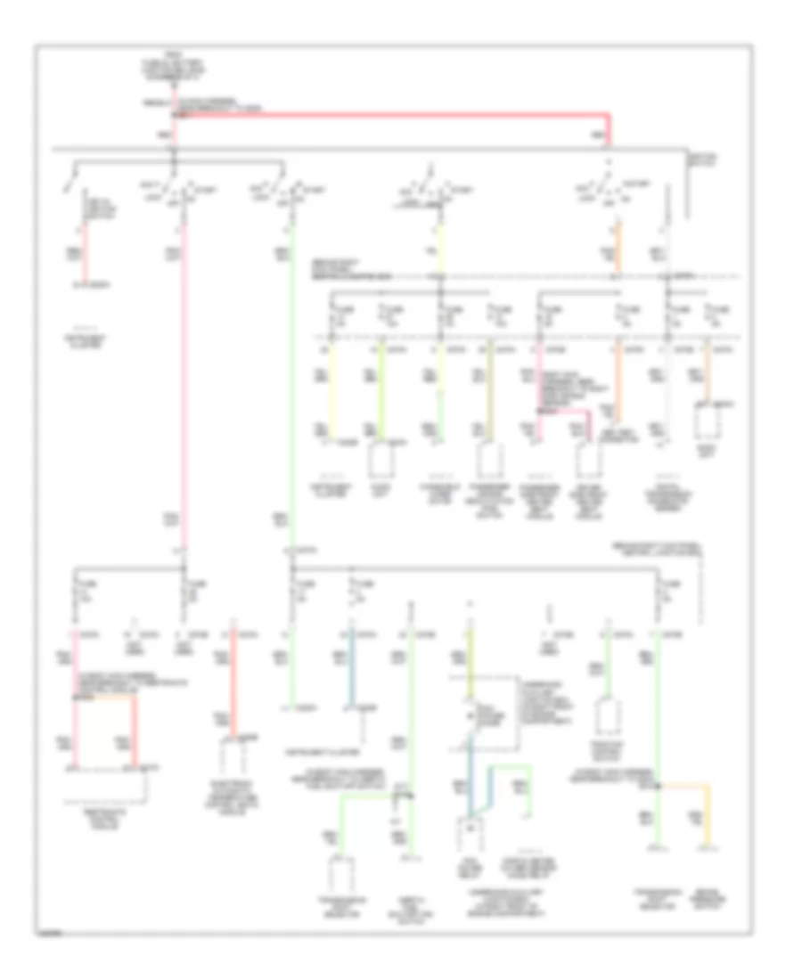
Power Distribution Wiring Diagram (3 of 4) for Ford Thunderbird 2005
List of elements for Power Distribution Wiring Diagram (3 of 4) for Ford Thunderbird 2005:
- (behind right kick panel) central junction box
- (below right side of dash panel) g203
- (in dash panel to headlamp junction harness, in breakout to abs test connector) s120
- (in dash panel to headlamp junction harness, in breakout to underhood auxiliary junction box) s110
- (in front side lamp harness, near breakout for c133) s117
- (in main harness, near breakout to right center image speaker) s208
- (in right front of engine compartment) underhood auxiliary junction box
- A/c clutch relay
- Abs control module
- Abs test connector
- Audio unit
- Auxiliary coolant pump relay
- Blower motor relay
- Brake pedal position switch
- C175b
- C201c
- C220a
- C220b
- C228b
- C240a
- C265b
- C270a
- C270b
- C270c
- C270d
- Center image amplifier
- Coolant control valve solenoid
- Cops & heated oxygen sensor (ho2s) relay
- Data link connector (dlc)
- Electronic automatic temperature control (eatc) module
- Engine cooling fan motor
- Exterior rear view mirror switch
- From fuse 14 h (diagram 3 of 4)
- From fuse 25 battery junction box (bjb) (diagram 2 of 4)
- From mega fuse 18 (diagram 1 of 4)
- Front cigar lighter
- Front electronic module (fem)
- Fuse 10a
- Fuse 15a
- Fuse 20a
- Fuse 30a
- Fuse 40a
- Fuse 5a
- Fuse 60a
- G203 (below right side of dash panel)
- Horn relay
- Instrument cluster
- Left driving lamp
- Nca
- Off
- Pcm power relay
- Power point
- Powertrain control module (pcm)
- Red
- Remote keyless entry module
- Right driving lamp
- S112 (in dash panel to headlamp junction harness, in breakout to underhood auxiliary junction box)
- Starter relay
- Stud junction box
- Sunload sensor
- To fuse 1 (diagram 3 of 4)
- Underhood auxiliary junction box (in right front of engine compartment)
- Windshield wiper motor
Power Distribution Wiring Diagram (4 of 4) for Ford Thunderbird 2005
List of elements for Power Distribution Wiring Diagram (4 of 4) for Ford Thunderbird 2005:
- (a/t)
- (behind right kick panel) central junction box
- (in body main harness, near breakout to g204) s218
- (in body main harness, near breakout to inertia fuel shut-off switch)
- (in body main harness, near breakout to restraints control module) s302
- (not used)
- A/t
- Abs test connector
- Acc
- Audio unit
- Brake pressure switch
- C220a
- C220b
- C228b
- C240a
- C270a
- C270b
- C270c
- C270d
- C270e
- C310a
- Cops & heated oxygen sensor (ho2s) relay
- Digital transmission range (dtr) sensor
- Driver side front heated seat module
- Electronic automatic temperature control (eatc) module
- From fuse 22, battery junction box (bjb) (diagram 2 of 4)
- Fuse 10a
- Fuse 3a
- Fuse 5a
- Ignition switch
- Inertia fuel shutoff (ifs) switch
- Instrument cluster
- Key-in ignition switch
- Lock
- Near breakout to g200) s211
- Off
- Passenger air bag deactivation (pad) switch
- Passenger side front heated seat module
- Pcm power diode
- Pcm power relay
- Red
- Restraints control module
- S216
- Start
- Traction control switch
- Transmission shift selector
- Underhood auxiliary junction box (in right front of engine compartment)
- Windshield wiper motor