POWER DISTRIBUTION
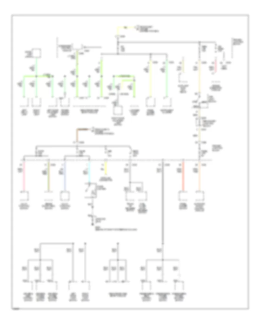
Power Distribution Wiring Diagram (1 of 4) for Ford Thunderbird Super Coupe 1995

List of elements for Power Distribution Wiring Diagram (1 of 4) for Ford Thunderbird Super Coupe 1995:
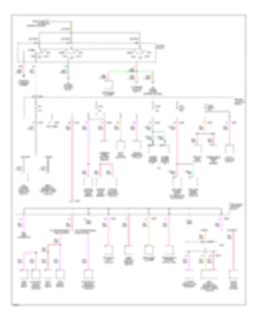
Power Distribution Wiring Diagram (2 of 4) for Ford Thunderbird Super Coupe 1995
List of elements for Power Distribution Wiring Diagram (2 of 4) for Ford Thunderbird Super Coupe 1995:
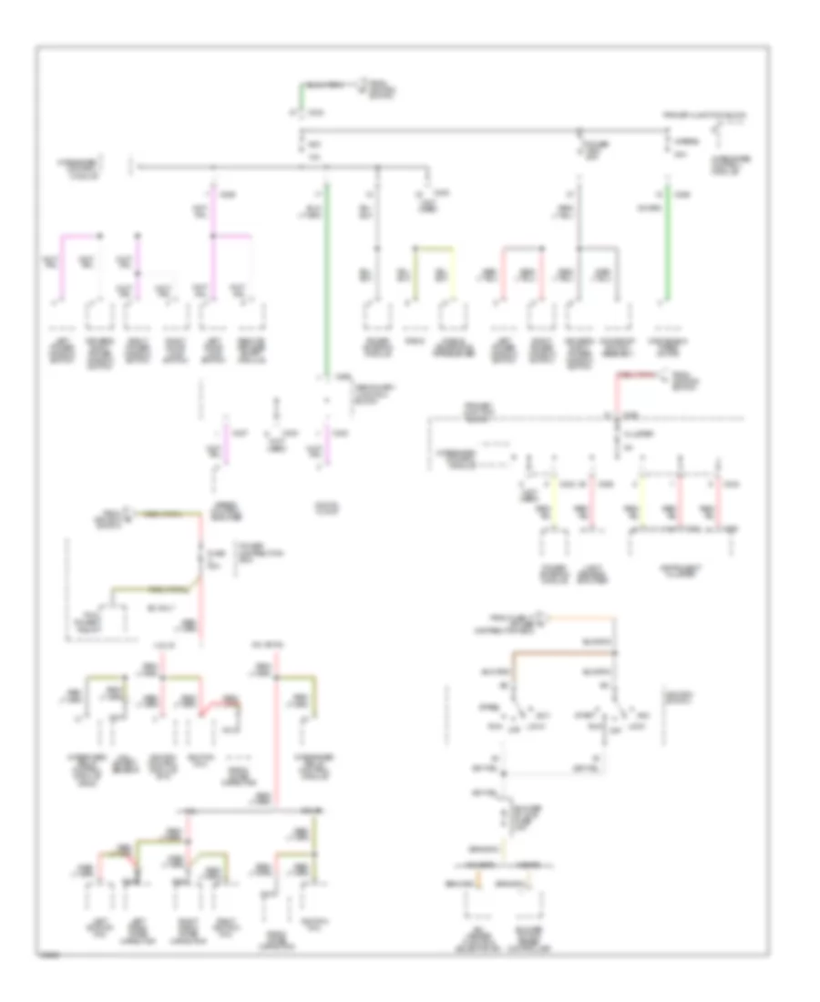
Power Distribution Wiring Diagram (3 of 4) for Ford Thunderbird Super Coupe 1995
List of elements for Power Distribution Wiring Diagram (3 of 4) for Ford Thunderbird Super Coupe 1995:
Power Distribution Wiring Diagram (4 of 4) for Ford Thunderbird Super Coupe 1995
List of elements for Power Distribution Wiring Diagram (4 of 4) for Ford Thunderbird Super Coupe 1995: